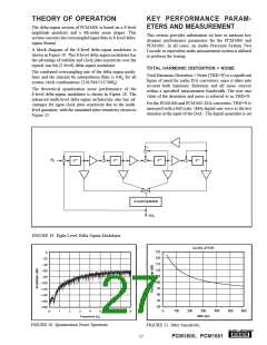
to 24-bit audio word length and a sampling frequency of
44.1kHz, or 96kHz. The digital generator output is taken
from the unbalanced S/PDIF connector of the measurement
system. The S/PDIF data is transmitted via coaxial cable to
the digital audio receiver on the DEM-DAI1600 demo board.
The receiver is then configured to output 24-bit data in either
I2S or left-justified data format. The DAC audio interface
format is programmed to match the receiver output format.
The analog output is then taken from the DAC post filter and
connected to the analog analyzer input of the measurment
system. The analog input is band limited using filters resi-
dent in the analyzer. The resulting THD+N is measured by
the analyzer and displayed by the measurement system.
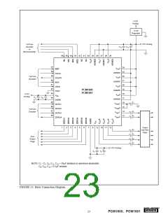
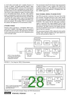
The measurement setup for the dynamic range measurement
is shown in Figure 23, and is similar to the THD+N test
setup discussed previously. The differences include the band
limit filter selection, the additional A-Weighting filter, and
the –60dBFS input level.
IDLE CHANNEL SIGNAL-TO-NOISE RATIO
The SNR test provides a measure of the noise floor of the
D/A converter. The input to the D/A is all 0’s data, and the
D/A converter’s Infinite Zero Detect Mute function must
be disabled (default condition at power up for the PCM1600,
PCM1601). This ensures that the delta-sigma modulator
output is connected to the output amplifier circuit so that
idle tones (if present) can be observed and effect the SNR
measurement. The dither function of the digital generator
must also be disabled to ensure an all ‘0’s data stream at the
input of the D/A converter.
DYNAMIC RANGE
Dynamic range is specified as A-Weighted, THD+N mea-
sured with a –60dBFS, 1kHz digital sine wave stimulus at
the input of the D/A converter. This measurment is designed
to give a good indicator of how the DAC will perform given
a low-level input signal.
The measurement setup for SNR is identical to that used for
dynamic range, with the exception of the input signal level.
(see the notes provided in Figure 23).
Evaluation Board
DEM-DAI1600
2nd-Order
Low-Pass
Filter
S/PDIF
Receiver
PCM1600
PCM1601
f
–3dB = 54kHz
Analyzer
and
Display
Digital
Generator
S/PDIF
Band Limit
Notch Filter
fC = 1kHz
Output
100% Full Scale
RMS Mode
HPF = 22Hz(1)
LPF = 30kHz(1)
Option = 20kHz Apogee Filter(2)
24-Bit, 1kHz
Sine Wave
NOTES: (1) There is little difference
in measured THD+N when using the
various settings for these filters.
(2) Required for THD+N test.
FIGURE 22. Test Setup for THD+N Measurements.
Evaluation Board
DEM-DAI1600
2nd-Order
Low-Pass
Filter
PCM1600(1)
PCM1601
S/PDIF
Receiver
f
–3dB = 54kHz
Analyzer
and
Display
Digital
Generator
A-Weight
Filter(1)
S/PDIF
Output
Band Limit
Notch Filter
C = 1kHz
0% Full Scale,
Dither Off (SNR)
–60dBFS,
RMS Mode
HPF = 22Hz
LPF = 22kHz
Option = A-Weighting(2)
f
NOTES: (1) Infinite Zero Detect Mute disabled.
(2) Results without A-Weighting will be
approximately 3dB worse.
1kHz Sine Wave
(Dynamic Range)
FIGURE 23. Test Set-Up for Dynamic Range and SNR Meeasurements.
®
28
PCM1600, PCM1601

 BB [ BURR-BROWN CORPORATION ]