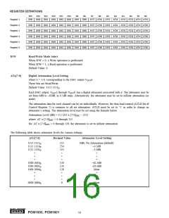
B15
R/W
B14
B13
B12
B11
B10
B9
B8
B7
B6
B5
B4
B3
B2
B1
B0
REGISTER 8
IDX6
IDX5
IDX4
IDX3
IDX2
IDX1
IDX0
res
INZD
DAC6 DAC5 DAC4 DAC3 DAC2 DAC1
R/W
Read/Write Mode Select
When R/W = 0, a Write operation is performed.
When R/W = 1, a Read operation is performed.
Default Value: 0
INZD
Infinite Zero Detect Mute Control
This bit is Read/Write.
Default Value: 0
INZD = 0
INZD = 1
Infinite Zero Detect Mute Disabled (default)
Infinite Zero Detect Mute Enabled
The INZD bit is used to enable or disable the Zero Detect Mute function described in the Zero Flag and Infinite
Zero Detect Mute section in this data sheet. The Zero Detect Mute function is independent of the Zero Flag
output operation, so enabling or disabling the INZD bit has no effect on the Zero Flag outputs (ZERO1-ZERO6,
ZEROA).
DACx
DAC Operation Control
where x = 1-6, corresponding to the DAC output VOUTx.
These bits are Read/Write.
Default Value: 0
DACx = 0
DACx = 1
DAC Operation Enabled (default)
DAC Operation Disabled
The DAC operation controls are used to enable and disable the DAC outputs, VOUT1 through VOUT6. When
DACx = 0, the output amplifier input is connected to the DAC output. When DACx = 1, the output amplifier
input is switched to the DC common-mode voltage (VCOM1 or VCOM2), equal to VCC/2.
®
18
PCM1600, PCM1601

 BB [ BURR-BROWN CORPORATION ]