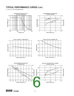
TYPICAL PERFORMANCE CURVES (CONT)
TA = +25°C, VCC = ±15V unless otherwise noted.
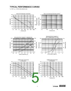
TOTAL HARMONIC DISTORTION
vs FREQUENCY
SETTLING TIME vs CLOSED-LOOP GAIN
10
8
0.01
0.008
0.006
0.004
0.002
0
G = +1
VO = 7Vrms
6
4
2
Test Equipment
Limit
0
1
10
100
1k
100
1k
10k
100k
Closed-Loop Gain (V/V)
Frequency (Hz)
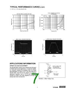
LARGE SIGNAL TRANSIENT RESPONSE
SMALL SIGNAL TRANSIENT RESPONSE
+15
+80
+40
0
0
+40
–80
–15
0
2.5
5
0
0.5
1
Time (µs)
Time (µs)
+VCC
APPLICATIONS INFORMATION
(1)
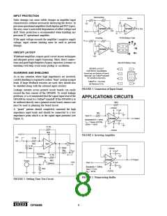
OFFSET VOLTAGE ADJUSTMENT
NOTE: (1) 10kΩ to 1MΩ
Trim Potentiometer
The OPA606 offset voltage is laser-trimmed and will require
no further trim for most applications. As with most amplifi-
ers, externally trimming the remaining offset can change
drift performance by about 0.5µV/°C for each millivolt of
adjusted offset. Note that the trim (Figure 1) is similar to
operational amplifiers such as LF156 and OP-16. The
OPA606 can replace most other amplifiers by leaving the
external null circuit unconnected.
(100kΩ Recommended)
100kΩ
7
1
5
2
6
OPA606
3
±50mV Typical
Trim Range
4
–VCC
FIGURE 1. Offset Voltage Trim.
®
7
OPA606

 BB [ BURR-BROWN CORPORATION ]