in a complete design (including heat sink) increase the
ambient temperature until the thermal protection is trig-
gered. Use worst-case load and signal conditions. For good
reliability, thermal protection should trigger more than 35°C
above the maximum expected ambient condition of your
application. This produces a junction temperature of 125°C
at the maximum expected ambient condition.
screw torque, insulating material used (if any), and thermal
joint compound used (if any) also affect θCH. A typical θCH
for a mounted 11-lead power ZIP package is 0.5°C/W. Now
we can solve for θHA
:
θHA = [(TJ – TA)/PD] – θJC – θCH
θHA = [(125°C – 40°C)/10W] – 1.4°C/W – 0.5°C/W
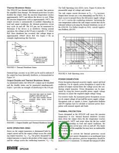
The internal protection circuitry of the OPA549 was de-
signed to protect against overload conditions. It was not
intended to replace proper heat sinking. Continuously run-
ning the OPA549 into thermal shutdown will degrade reli-
ability.
θHA = 6.6°C/W
To maintain junction temperature below 125°C, the heat
sink selected must have a θHA less than 6.6°C/W. In other
words, the heat sink temperature rise above ambient must be
less than 66°C (6.6°C/W • 10W). For example, at 10W
Thermalloy model number 6396B has a heat sink tempera-
ture rise of 56°C (θHA = 56°C/10W = 5.6°C/W), which is
below the required 66°C required in this example. Thermalloy
model number 6399B has a sink temperature rise of 33°C
(θHA = 33°C/10W = 3.3°C/W), which is also below the
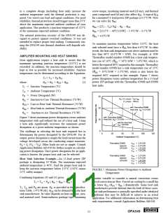
required 66°C required in this example. Figure 7 shows
power dissipation versus ambient temperature for a 11-lead
power ZIP package with the Thermalloy 6396B and 6399B
heat sinks.
AMPLIFIER MOUNTING AND HEAT SINKING
Most applications require a heat sink to assure that the
maximum operating junction temperature (125°C) is not
exceeded. In addition, the junction temperature should be
kept as low as possible for increased reliability. Junction
temperature can be determined according to the Equations:
TJ = TA + PD θJA
(4)
(5)
where
θJA = θJC + θCH + θHA
TJ = Junction Temperature (°C)
TA = Ambient Temperature (°C)
PD = Power Dissipated (W)
30
PD = (TJ (max) – TA)/ θJA
(TJ (max) – 150°C)
θJC = Junction-to-Case Thermal Resistance (°C/W)
θCH = Case-to-Heat Sink Thermal Resistance (°C/W)
θHA = Heat Sink-to-Ambient Thermal Resistance (°C/W)
with Thermalloy 6399B
20
Heat Sink,
θ
JA = 5.2°C/W
θJA
=
Junction-to-Air Thermal Resistance (°C/W)
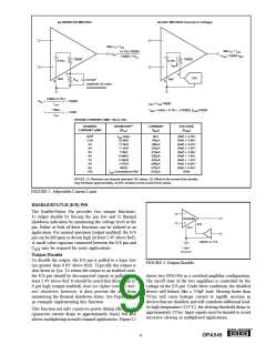
Figure 7 shows maximum power dissipation versus ambient
temperature with and without the use of a heat sink. Using
a heat sink significantly increases the maximum power
dissipation at a given ambient temperature as shown.
with Thermalloy 6396B
Heat Sink, JA = 7.5°C/W
θ
10
0
with No Heat Sink,
θ
JA = 30°C/W
The challenge in selecting the heat sink required lies in
determining the power dissipated by the OPA549. For dc
output, power dissipation is simply the load current times the
voltage developed across the conducting output transistor,
PD = IL (VS – VO). Other loads are not as simple. Consult
Application Bulletin AB-039 for further insight on calculat-
ing power dissipation. Once power dissipation for an appli-
cation is known, the proper heat sink can be selected.
0
25
50
75
100
125
Ambient Temperature (°C)
Thermalloy 6396B
assume
θ HA = 5.6°C/W
θ CH = 0.5°C/W
θ JC = 1.4°C/W
θ JA = 7.5°C/W
OPA549
Thermalloy 6396B
assume
θ HA = 3.3°C/W
θ CH = 0.5°C/W
θ JC = 1.4°C/W
θ JA = 5.2°C/W
Heat Sink Selection Example—An 11-lead power ZIP
package is dissipating 10 Watts. The maximum expected
ambient temperature is 40°C. Find the proper heat sink to
keep the junction temperature below 125°C (150°C minus
25°C safety margin).
OPA549
FIGURE 7. Maximum Power Dissipation vs Ambient
Temperature.
Combining Equations (4) and (5) gives:
Another variable to consider is natural convection versus
forced convection air flow. Forced-air cooling by a small fan
can lower θCA (θCH + θHA ) dramatically. Some heat sink
manufacturers provide thermal data for both of these cases.
Heat sink performance is generally specified under idealized
conditions that may be difficult to achieve in an actual
application. For additional information on determining heat
sink requirements, consult Application Bulletin AB-038.
TJ = TA + PD ( θJC + θCH + θHA
)
(6)
TJ, TA, and PD are given. θJC is provided in the Specifica-
tions Table, 1.4°C/W (dc). θCH can be obtained from the heat
sink manufacturer. Its value depends on heat sink size, area,
and material used. Semiconductor package type, mounting
®
11
OPA549

 BB [ BURR-BROWN CORPORATION ]