TYPICAL APPLICATIONS
R1
R2
100kΩ
10kΩ
V1
+60V
+40V
0.1µF
25kΩ
OPA445
0-2mA
R5
100Ω
–40V
DAC80-CBI-I
OPA445
V2
VO = 0 to +50V
at 10mA
Protects DAC
During Slewing
R3
100kΩ
R4
9.9kΩ
0.1µF
Load
IL
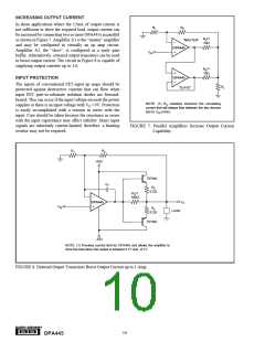
IL = [(V2 – V1)/R5] (R2/R1)
= (V2 – V1)/1kΩ
–12V
Compliance Voltage Range = ±35V
NOTE: R1 = R3 and R2 = R4 + R5
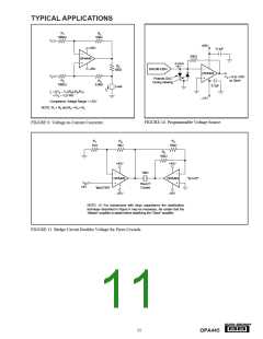
FIGURE 10. Programmable Voltage Source.
FIGURE 9. Voltage-to-Current Converter.
R1
R2
R3
1kΩ
9kΩ
10kΩ
R4
10kΩ
+45V
+45V
OPA445
–45V
160V
OPA445
“SLAVE”
VIN
Piezo(1)
Crystal
±4V
“MASTER”
–45V
NOTE: (1) For transducers with large capacitance the stabilization
technique described in Figure 6 may be necessary. Be certain that the
“Master” amplifier is stable before stabilizing the “Slave” amplifier.
FIGURE 11. Bridge Circuit Doubles Voltage for Piezo Crystals.
®
11
OPA445

 BB [ BURR-BROWN CORPORATION ]