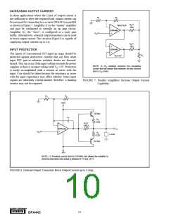
INCREASING OUTPUT CURRENT
In those applications where the 15mA of output current is
not sufficient to drive the required load, output current can
be increased by connecting two or more OPA445s in parallel
as shown in Figure 7. Amplifier A1 is the “master” amplifier
and may be configured in virtually an op amp circuit.
Amplifier A2, the “slave”, is configured as a unity gain
buffer. Alternatively, external output transistors can be used
to boost output current. The circuit in Figure 8 is capable of
supplying output currents up to 1A.
R1
R2
(1)
RS
“MASTER”
10Ω
OPA445
VIN
(1)
RS
10Ω
OPA445
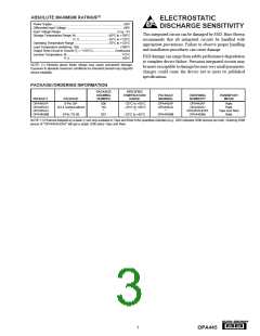
INPUT PROTECTION
The inputs of conventional FET-input op amps should be
protected against destructive currents that can flow when
input FET gate-to-substrate isolation diodes are forward-
biased. This can occur if the input voltage exceeds the power
supplies or there is an input voltage with VS = 0V. Protection
is easily accomplished with a resistor in series with the
input. Care should be taken because the resistance in series
with the input capacitance may affect stability. Many input
signals are inherently current-limited, therefore, a limiting
resistor may not be required.
RL
“SLAVE”
NOTE: (1) RS resistors minimize the circulating
current that will always flow between the two devices
due to VOS errors.
FIGURE 7. Parallel Amplifiers Increase Output Current
Capability.
R1
R2
+45V
TIP29C
R4
CF
0.2Ω
(1)
R3
100Ω
VO
OPA445
VIN
R4
LOAD
0.2Ω
TIP30C
–45V
NOTE: (1) Provides current limit for OPA445 and allows the amplifier to
drive the load when the output is between 0.7V and –0.7V.
FIGURE 8. External Output Transistors Boost Output Current up to 1 Amp.
®
10
OPA445

 BB [ BURR-BROWN CORPORATION ]