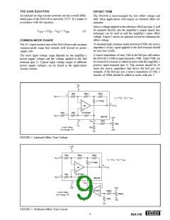
Preferably, the offset trim voltage applied to the Ref pin
should be buffered with an amp such as an OPA237
(see Figure 3). In this case, the op amp output impedance is
low enough that no external resistor is needed to maintain
the INA148’s excellent CMR.
Unless the shunt resistor is less than approximately 100Ω, an
additional equal compensating resistor (RC) is recommended
to maintain input balance and high CMR.
Source impedances (or shunts) greater than 5kΩ are not
recommended, even if they are “perfectly” compensated.
This is because the internal resistor network is laser-trimmed
for accurate voltage divider ratios, but not necessarily to
absolute values. Input resistors are shown as 1MΩ, however,
this is only their nominal value.
INPUT IMPEDANCE
The input resistor network determines the impedance of
each of the INA148’s inputs. It is approximately 1MΩ.
Unlike an instrumentation amplifier, signal source imped-
ances at the two input terminals must be nearly equal to
maintain good common-mode rejection.
In practice, the input resistors’ absolute values may vary by
as much as 30 percent. The two input resistors match to
about 5 percent, so adding compensating resistors greater
than 5kΩ can cause a serious mismatch in the resulting
resistor network voltage divider ratios, thus degrading CMR.
A mismatch between the two inputs’ source impedances will
cause a differential amplifier’s common-mode rejection to
be degraded. With a source impedance imbalance of only
500Ω, CMR can fall to approximately 66dB.
Attempts to extend the INA148 input voltage range by
adding external resistors is not recommended for the reasons
just described in the last paragraph. CMR will suffer a
serious degradation unless the resistors are carefully trimmed
for CMR and gain. This is an iterative adjustment and can be
tedious and time consuming.
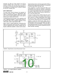
Figure 4 shows a common application—measuring power
supply current through a shunt resistor (RS). A shunt resistor
creates an unbalanced source resistance condition that can
degrade a differential amplifier’s common mode rejection.
+15V
7
LOAD
1MΩ
50kΩ
50kΩ
2
VO = IL • RS
IL
2.7778kΩ
6
VO
A1
RS
52.6316kΩ
RC
1MΩ
3
INA148
VCM
4
1
200V
–15V
Make RC = RS if RS ≥ 100Ω
FIGURE 4. Shunt-Resistor Current Measurement Circuit.
+15V
C1
4.7µF(1)
7
250V
1MΩ
50kΩ
50kΩ
2
VI–N
VO = (VI+N – VI–N
)
2.7778kΩ
6
VCM = 200Vpk
VO
A1
C2
4.7µF(1)
250V
52.6316kΩ
1MΩ
3
VI+N
INA148
4
1
Typical CMR: 50Hz = 59dB
60Hz = 61dB
–15V
400Hz = 78dB
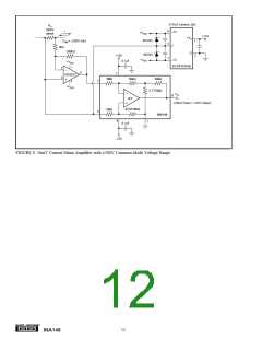
NOTE: (1) Metallized polypropylene, ±5% tolerance.
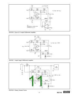
FIGURE 5. AC-Coupled Difference Amplifier.
®
10
INA148

 BB [ BURR-BROWN CORPORATION ]