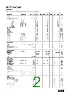
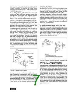
impedance (1010Ω) desirable in instrumentation amplifier
applications. The offset voltage, and offset voltage versus
temperature, are low due to the monolithic design, and
improved even further by state-of-the-art laser-trimming
techniques.
DISCUSSION OF
PERFORMANCE
INSTRUMENTATION AMPLIFIERS
Instrumentation amplifiers are differential-input closed-loop
gain blocks whose committed circuit accurately amplifies the
voltage applied to their inputs. They respond mainly to the
difference between the two input signals and exhibit ex-
tremely high input impedance, both differentially and com-
mon-mode. The feedback networks of this instrumentation
amplifier are included on the monolithic chip. No external
resistors are required for gains of 1, 10, 100, and 1000 in the
INA102.
The output stage (A3) is connected in a unity-gain differential
amplifier configuration. A critical part of this stage is the
matching of the four 20kΩ resistors which provide the
difference function. These resistors must be initially well
matched and the matching must be maintained over tempera-
ture and time in order to retain good common-mode rejec-
tion.
All of the internal resistors are made of thin-film nichrome
on the integrated circuit. The critical resistors are laser-
trimmed to provide the desired high gain accuracy and
common-mode rejection. Nichrome ensures long-term sta-
bility and provides excellent TCR and TCR tracking. This
provides gain accuracy and common-mode rejection when
the INA102 is operated over wide temperature ranges.
An operational amplifier, on the other hand, is an open-loop,
uncommitted device that requires external networks to close
the loop. While op amps can be used to achieve the same
basic function as instrumentation amplifiers, it is very diffi-
cult to reach the same level of performance. Using op amps
often leads to design tradeoffs when it is necessary to amplify
low-level signals in the presence of common-mode voltages
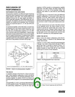
while maintaining high-input impedances. Figure 1 shows a
simplified model of an instrumentation amplifier that elimi-
nates most of the problems associated with op amps.
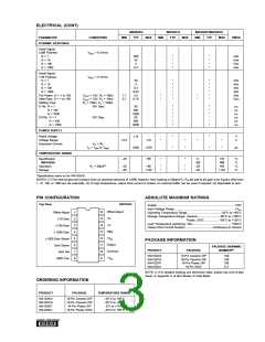
USING THE INA102
Figure 2 shows the simplest configuration of the INA102.
The output voltage is a function of the differential input
voltage times the gain.
A gain of 1, 10, 100, or 1000 is selected by programming pins
2 through 7 (see Table I). Notice that for the gain of 1000, a
special gain sense is provided to preserve accuracy. Al-
though this is not always required, gain errors caused by
external resistance in series with the low value 40.04Ω
internal gain set resistor are thus eliminated.
eO = eA + eB
eA = G(e2 – e1) = GeD
G(e2 + e1)/2
CMRR
GeCM
eB
=
=
CMRR
e2
ed /2
ZCM
~
~
eCM
GAIN
CONNECT PINS
Za
e0
Zd
~ ~
~
1
10
6 to 7
2 to 6 and 7
ea
ZCM
eb
e
d /2
100
1000
3 to 6 and 7
4 to 7 and separately 5 to 6
e1
TABLE I. Pin-Programmable Gain Connections.
GeCM
eO = GeD +
CMRR
Gain Set
Gain = 1
15
+In
7
Gain set is pin-programmable for x1, x10, x100, x1000 in the INA102.
Output
11
INA102
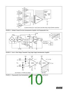
FIGURE 1. Model of an Instrumentation Amplifier.
6
12
14
10
–In
e2
THE INA102
9
~
10kΩ
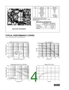
A simplified schematic of the INA102 is shown on the first
page. A three-amplifier configuration is used to provide the
desirable characteristics of a premium performance instru-
mentation amplifier. In addition, INA102 has features not
normally found in integrated circuit instrumentation amplifi-
ers.
–VCC
+VCC
~
1µF
Tantalum
1µF
Tantalum
The input buffers (A1 and A2) incorporate high performance,
low-drift amplifier circuitry. The amplifiers are connected in
the noninverting configuration to provide the high input
FIGURE 2. Basic Circuit Connection for the INA102.
®

 BB [ BURR-BROWN CORPORATION ]