e6
e4
e2
INA102
INA102
INA102
Channel
Select
e5
e3
e1
INA102
INA102
INA102
Control
Logic
Gain
Select
IN7
IN6
IN5
IN4
IN3
IN2
IN1
IN0
CP
CE
PGA100
eOUT
VREF
*
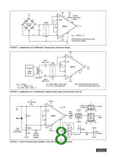
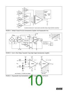
* As shown channels 0 and 1 may be used for auto offset zeroing, and gain calibration respectively.
FIGURE 11. Multiple Channel Precision Instrumentation Amplifier with Programmable Gain.
+24V
20
16
4
+10VREF
2N3055
15
3
7
6
14
15
12
4
3
5
16
12
INA102
1
–40
0
40
11
+2V to +10V
13
14
G
S
D
XTR110
300Ω
VIN
(mV)
10
2
±40mV
9
9
+24V
OPA27
40kΩ
60kΩ
10
4mA to 20mA
RL
V
L
+6V
G = 100
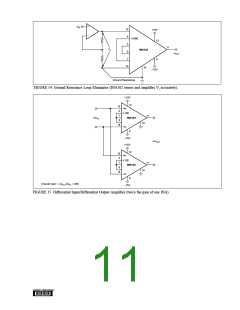
FIGURE 12. 4mA to 20mA Bridge Transmitter Using Single Supply Instrumentation Amplifier.
+15V
16
+15V
+15V
12
D
D
10kΩ
10kΩ
15
G = 1
G = 1, 10, 100
15
+In
–In
6
7
6
11
+15V
–15V
7
8
∆eIN
INA102
PGA102
eOUT
–15V
5
4
D
D
10
3
14
2
1
13
9
–15V
–15V
x10
x100
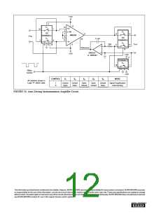
Input Protection: D = FDH300 (Low Leakage)
Gain Select
FIGURE 13. Programmable-Gain Instrumentation Amplifier Using the INA102 and PGA102.
®

 BB [ BURR-BROWN CORPORATION ]