+15V
11
S1
12
15
3
+In
x 100
1
4
16
3
S2
1/2
DG5043CJ
7
11
9
5
8
6
INA102
∆eIN
6
1/2
DG5043CJ
S3
0.1µF
10
14
–In
S4
eOUT
1kΩ
9
15 13 14
Reference
OPA111
10
–15V
+15V
11
or OPA121
DG5040CJ
S5
16
1
15 13 14
–15V
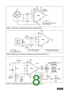
200µs
Control
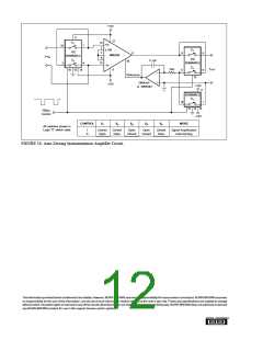
CONTROL
S1
S2
S3
S4
S5
MODE
All switches shown in
Logic “0” switch state.
1
0
Closed
Open
Closed
Open
Open
Closed
Open
Closed
Closed
Open
Signal Amplification
Auto-Zeroing
FIGURE 16. Auto-Zeroing Instrumentation Amplifier Circuit.
Theinformationprovidedhereinisbelievedtobereliable;however, BURR-BROWNassumesnoresponsibilityforinaccuraciesoromissions. BURR-BROWNassumes
no responsibility for the use of this information, and all use of such information shall be entirely at the user’s own risk. Prices and specifications are subject to change
without notice. No patent rights or licenses to any of the circuits described herein are implied or granted to any third party. BURR-BROWN does not authorize or warrant
any BURR-BROWN product for use in life support devices and/or systems.
®

 BB [ BURR-BROWN CORPORATION ]