SMPS Capacitors (CH Style)
Chip Assemblies
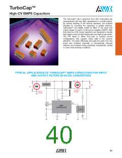
HORIZONTALLY MOUNTED ‘L’ LEAD SMT PRODUCT
DIMENSIONS
millimeters (inches)
No. of
Part Number format (CHxxxxxxxxxx0A7)
Typical Part Number CH411C275KA30A7
L
W
S
Style
Leads
(nom)
(max)
(max)
per side
W max
CH41-44 9.2 (0.362) 8.7 (0.342)
8.2 (0.322)
3
4
CH51-54 10.7 (0.421) 10.7 (0.421) 10.2 (0.400)
CH61-64 14.9 (0.586) 13.6 (0.535) 14.0 (0.551)
CH71-74 16.8 (0.661) 21.6 (0.850) 15.2 (0.600)
CH76-79 21.6 (0.850) 16.6 (0.653) 20.3* (0.800)
CH81-84 12.0 (0.472) 38.2 (1.503) 10.2 (0.400)
CH86-89 18.9 (0.744) 38.2 (1.503) 15.2 (0.600)
CH91-94 24.0 (0.944) 40.6 (1.598) 20.3* (0.800)
2.54 (0.1)
0.5 (0.02)
5
7
6
14
14
14
T max
L
max
S
0.5 (0.02)
2.54 (0.1)
0.5 (0.02)
*Tolerance 0.8 (0.031)
NOTE: A ‘L’ lead low profileversion
millimeters (inches)
(CH....0A5) is available with lead height
1.1 (0.043) max. for single chip assemblies eg.
CH415C225MA30A5
Style
T max
L2
L1
CH41/51/61/71/76/81/86/91
CH42/52/62/72/77/82/87/92
CH43/53/63/73/78/83/88/93
CH44/54/64/74/79/84/89/94
3.8 (0.150)
7.4 (0.291)
11.1 (0.437)
14.8 (0.583)
Lead width 0.5 (0.020)
Lead thickness 0.254 (0.010)
L1 = L2 0.5 (0.020)
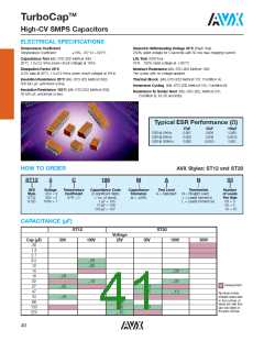
HORIZONTALLY MOUNTED ‘J’ LEAD SMT PRODUCT
Part Number format (CHxxxxxxxxxx0A8)
Typical Part Number CH411C275KA30A8
DIMENSIONS
millimeters (inches)
No. of
L
W
S
Style
Leads
(nom)
L1
L2
(max)
(max)
2.54 (0.100)
0.5 (0.020)
per side
CH41-44 9.2 (0.362) 8.7 (0.342)
CH51-54 10.7 (0.421) 10.7 (0.421)
CH61-64 14.9 (0.586) 13.6 (0.535)
CH71-74 16.8 (0.661) 21.6 (0.850)
8.2 (0.322)
10.2 (0.400)
14.0 (0.551)
15.2 (0.600)
3
4
5
7
6
T max
L
max
CH76-79 21.6 (0.850) 16.6 (0.653) 20.3* (0.800)
CH81-84 12.0 (0.472) 38.2 (1.503)
CH86-89 18.9 (0.744) 38.2 (1.503)
10.2 (0.400) 14
15.2 (0.600) 14
S
0.5 (0.020)
CH91-94 24.0 (0.944) 40.6 (1.598) 20.3* (0.800) 14
*Tolerance 0.8 (0.031)
W max
2.54 (0.100)
0.5 (0.020)
millimeters (inches)
Style
T max
NOTE: A ‘J’ lead low profileversion (CH....0A3) is available with lead height
1.1 (0.043) max. for single chip assemblies eg. CH515C475MA30A3
CH41/51/61/71/76/81/86/91
CH42/52/62/72/77/82/87/92
CH43/53/63/73/78/83/88/93
CH44/54/64/74/79/84/89/94
3.8 (0.150)
7.4 (0.291)
11.1 (0.437)
14.8 (0.583)
Lead width 0.5 (0.020)
Lead thickness 0.254 (0.010)
L1 = L2 0.5 (0.020)
HOW TO ORDER
CH
52
5
C
106
M
A
3
0
A
7
Style
Code
Size Voltage Dielectric Capacitance Capacitance Specification
Finish
Code
Lead Dia. Lead Space
Lead Style
Code
3 = Low profile ‘J’
(single chip)
5 = Low profile ‘L’
(single chip)
7 = ‘L’ Dual in line
8 = ‘J’ Dual in line
Code Code
Code
Code
(2 significant
digits + no.
of zeros)
eg. 105 = 1 μF
106 = 10 μF
107 = 100 μF
Tolerance
C0G: J = 5ꢀ
K = 10ꢀ
Code
Code
Code
A = Non-customized 3 = Uncoated
8 = Coated
(see product section)
5 = 50V
A = C0G
C = X7R
0 = Standard
A = Standard
1 = 100V
2 = 200V
7 = 500V
(classified as
uninsulated)
M = 20ꢀ
X7R: K = 10ꢀ
M = 20ꢀ
P = +100, -0ꢀ
Note: See page 109 for How to Order BS9100 parts
36

 KYOCERA AVX [ KYOCERA AVX ]