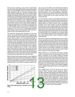
The first step in selecting a sense resistor is determining
how much current the resistor will be sensing.The graph in
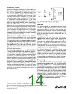
Figure 2ꢀ shows the RMS current in each phase of a three-
phase induction motor as a function of average motor
output power (in horsepower, hp) and motor drive supply
tance increases. This effect can be minimized by reducing
the thermal resistance of the current sensing resistor or
by using a resistor with a lower tempco. Lowering the
thermal resistance can be accomplished by reposition-
ing the current sensing resistor on the PC board, by using
voltage. The maximum value of the sense resistor is deter- larger PC board traces to carry away more heat, or by
mined by the current being measured and the maximum
recommended input voltage of the isolation amplifier. The
maximum sense resistance can be calculated by taking
the maximum recommended input voltage and dividing
by the peak current that the sense resistor should see
during normal operation. For example, if a motor will have
a maximum RMS current of ±0 A and can experience up
to ꢁ01 overloads during normal operation, then the peak
current is 2±.± A (=±0 x ±.4±4 x ±.ꢁ). Assuming a maximum
input voltage of 200 mV, the maximum value of sense re-
sistance in this case would be about ±0 mΩ.
using a heat sink.
For a two-terminal current sensing resistor, as the value of
resistance decreases, the resistance of the leads become a
significant percentage of the total resistance. This has two
primary effects on resistor accuracy. First, the effective
resistance of the sense resistor can become dependent
on factors such as how long the leads are, how they are
bent, how far they are inserted into the board, and how far
solder wicks up the leads during assembly (these issues
will be discussed in more detail shortly). Second, the leads
are typically made from a material, such as copper, which
has a much higher tempco than the material from which
the resistive element itself is made, resulting in a higher
The maximum average power dissipation in the sense
resistor can also be easily calculated by multiplying the
sense resistance times the square of the maximum RMS tempco overall.
current, which is about ± W in the previous example. If
Both of these effects are eliminated when a four-terminal
the power dissipation in the sense resistor is too high, the
resistance can be decreased below the maximum value
to decrease power dissipation. The minimum value of the
sense resistor is limited by precision and accuracy require-
ments of the design. As the resistance value is reduced,
the output voltage across the resistor is also reduced,
which means that the offset and noise, which are fixed,
become a larger percentage of the signal amplitude. The
selected value of the sense resistor will fall somewhere
current sensing resistor is used. A four-terminal resistor has
two additional terminals that are Kelvin connected directly
across the resistive element itself; these two terminals are
used to monitor the voltage across the resistive element
while the other two terminals are used to carry the load
current. Because of the Kelvin connection, any voltage
drops across the leads carrying the load current should
have no impact on the measured voltage.
between the minimum and maximum values, depending When laying out a PC board for the current sensing
on the particular requirements of a specific design.
resistors, a couple of points should be kept in mind. The
Kelvin connections to the resistor should be brought
together under the body of the resistor and then run very
close to each other to the input of the ACPL-C79B/C79A/
C790; this minimizes the loop area of the connection and
reduces the possibility of stray magnetic fields from inter-
fering with the measured signal. If the sense resistor is not
located on the same PC board as the isolation amplifier
circuit, a tightly twisted pair of wires can accomplish the
same thing.
When sensing currents large enough to cause significant
heating of the sense resistor, the temperature coefficient
(tempco) of the resistor can introduce nonlinearity due to
the signal dependent temperature rise of the resistor. The
effect increases as the resistor-to-ambient thermal resis-
40
440 V
35
380 V
220 V
120 V
30
Also, multiple layers of the PC board can be used to
increase current carrying capacity. Numerous plated-
through vias should surround each non-Kelvin terminal of
the sense resistor to help distribute the current between
the layers of the PC board. The PC board should use 2 or
4 oz. copper for the layers, resulting in a current carrying
capacity in excess of 20 A. Making the current carrying
traces on the PC board fairly large can also improve the
sense resistor’s power dissipation capability by acting as a
heat sink. Liberal use of vias where the load current enters
and exits the PC board is also recommended.
25
20
15
10
5
0
0
5
10
15
20
25
30
35
MOTOR PHASE CURRENT - A (rms)
Figure 23. Motor output horsepower vs. motor phase current and supply
voltage.
±ꢀ

 AVAGO [ AVAGO TECHNOLOGIES LIMITED ]