Definitions
Gain
Common Mode Transient Immunity, CMTI, also known as Com-
mon Mode Rejection
Gain is defined as the slope of the best-fit line of differen-
tial output voltage (V + – V –) vs. differential input
CMTI is tested by applying an exponentially rising/falling
voltage step on pin 4 (GND±) with respect to pin ꢁ (GND2).
The rise time of the test waveform is set to approximately
ꢁ0 ns. The amplitude of the step is adjusted until the dif-
OUT
OUT
voltage (V + – V –) over the nominal input range, with
IN
IN
offset error adjusted out.
Nonlinearity
ferential output (V + – V –) exhibits more than a 200
OUT
OUT
Nonlinearity is defined as half of the peak-to-peak output
deviation from the best-fit gain line, expressed as a per-
centage of the full-scale differential output voltage.
mV deviation from the average output voltage for more
than ±µs. The ACPL-C79B/C79A/C790 will continue to
function if more than ±0 kV/μs common mode slopes are
applied, as long as the breakdown voltage limitations are
observed.
Input DC Common Mode Rejection Ratio, CMRR
IN
CMRR is defined as the ratio of the differential signal
IN
Power Supply Rejection, PSR
gain (signal applied differentially between pins V + and
OUT
V
–) to the input side common-mode gain (input pins
OUT
PSR is the ratio of differential amplitude of the ripple
outputs over power supply ripple voltage, referred to the
input, expressed in dB.
tied together and the signal applied to both inputs with
respect to pin GND±), expressed in dB.
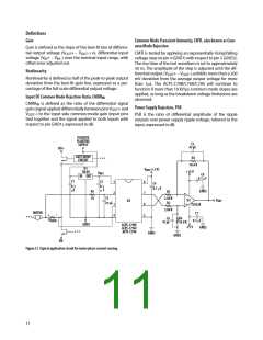
POSITIVE
FLOATING
C5
SUPPLY
47 pF
HV+
GATE DRIVE
R3
* * *
CIRCUIT
10.0 K
U1
V
DD2 (+5 V)
C4
+15 V
78L05
VDD1
C8
IN OUT
0.1 µF
C1
C2
0.1
1
2
8
0.1
0.1 µF
µF
µ F
GND2
R5
10
R1
7
6
5
–
C3
47 nF
2.00 K
R2
U3
+
VOUT
U2
3
4
TL032A
2.00 K
MOTOR
C7
+
–
* * *
C6
R4
RSENSE
0.1 µF
47 pF
10.0 K
GND1
ACPL-C79B/
ACPL-C79A/
ACPL-C790
-15 V
GND2
* * *
GND2
GND2
HV-
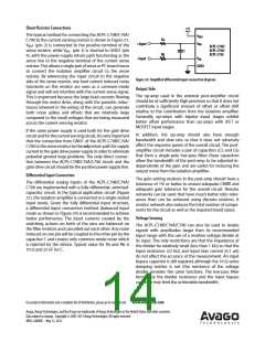
Figure 21. Typical application circuit for motor phase current sensing.
±±

 AVAGO [ AVAGO TECHNOLOGIES LIMITED ]