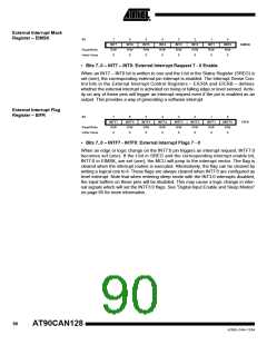
External Interrupt Mask
Register – EIMSK
Bit
7
6
5
4
3
2
1
0
IINT0
R/W
0
INT7
R/W
0
INT6
R/W
0
INT5
R/W
0
INT4
R/W
0
INT3
R/W
0
INT2
R/W
0
INT1
R/W
0
EIMSK
Read/Write
Initial Value
• Bits 7..0 – INT7 – INT0: External Interrupt Request 7 - 0 Enable
When an INT7 – INT0 bit is written to one and the I-bit in the Status Register (SREG) is
set (one), the corresponding external pin interrupt is enabled. The Interrupt Sense Con-
trol bits in the External Interrupt Control Registers – EICRA and EICRB – defines
whether the external interrupt is activated on rising or falling edge or level sensed. Activ-
ity on any of these pins will trigger an interrupt request even if the pin is enabled as an
output. This provides a way of generating a software interrupt.
External Interrupt Flag
Register – EIFR
Bit
7
INTF7
R/W
0
6
INTF6
R/W
0
5
INTF5
R/W
0
4
INTF4
R/W
0
3
INTF3
R/W
0
2
INTF2
R/W
0
1
INTF1
R/W
0
0
IINTF0
R/W
0
EIFR
Read/Write
Initial Value
• Bits 7..0 – INTF7 - INTF0: External Interrupt Flags 7 - 0
When an edge or logic change on the INT7:0 pin triggers an interrupt request, INTF7:0
becomes set (one). If the I-bit in SREG and the corresponding interrupt enable bit,
INT7:0 in EIMSK, are set (one), the MCU will jump to the interrupt vector. The flag is
cleared when the interrupt routine is executed. Alternatively, the flag can be cleared by
writing a logical one to it. These flags are always cleared when INT7:0 are configured as
level interrupt. Note that when entering sleep mode with the INT3:0 interrupts disabled,
the input buffers on these pins will be disabled. This may cause a logic change in inter-
nal signals which will set the INTF3:0 flags. See “Digital Input Enable and Sleep Modes”
on page 65 for more information.
90
AT90CAN128
4250E–CAN–12/04

 ATMEL [ ATMEL ]