External Interrupts
The External Interrupts are triggered by the INT7:0 pins. Observe that, if enabled, the
interrupts will trigger even if the INT7:0 pins are configured as outputs. This feature pro-
vides a way of generating a software interrupt. The External Interrupts can be triggered
by a falling or rising edge or a low level. This is set up as indicated in the specification for
the External Interrupt Control Registers – EICRA (INT3:0) and EICRB (INT7:4). When
the external interrupt is enabled and is configured as level triggered, the interrupt will
trigger as long as the pin is held low. Note that recognition of falling or rising edge inter-
rupts on INT7:4 requires the presence of an I/O clock, described in “Clock Systems and
their Distribution” on page 34. Low level interrupts and the edge interrupt on INT3:0 are
detected asynchronously. This implies that these interrupts can be used for waking the
part also from sleep modes other than Idle mode. The I/O clock is halted in all sleep
modes except Idle mode.
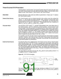
Note that if a level triggered interrupt is used for wake-up from Power-down mode, the
changed level must be held for some time to wake up the MCU. This makes the MCU
less sensitive to noise. The changed level is sampled twice by the Watchdog Oscillator
clock. The period of the Watchdog Oscillator is 1 µs (nominal) at 5.0V and 25°C. The
frequency of the Watchdog Oscillator is voltage dependent as shown in the “Electrical
Characteristics(1)” on page 355. The MCU will wake up if the input has the required
level during this sampling or if it is held until the end of the start-up time. The start-up
time is defined by the SUT fuses as described in “System Clock” on page 34. If the level
is sampled twice by the Watchdog Oscillator clock but disappears before the end of the
start-up time, the MCU will still wake up, but no interrupt will be generated. The required
level must be held long enough for the MCU to complete the wake up to trigger the level
interrupt.
External Interrupt Control
Register A – EICRA
Bit
7
ISC31
R/W
0
6
ISC30
R/W
0
5
ISC21
R/W
0
4
ISC20
R/W
0
3
ISC11
R/W
0
2
ISC10
R/W
0
1
ISC01
R/W
0
0
ISC00
R/W
0
EICRA
Read/Write
Initial Value
• Bits 7..0 – ISC31, ISC30 – ISC01, ISC00: External Interrupt 3 - 0 Sense Control
Bits
The External Interrupts 3 - 0 are activated by the external pins INT3:0 if the SREG I-flag
and the corresponding interrupt mask in the EIMSK is set. The level and edges on the
external pins that activate the interrupts are defined in Table 50. Edges on INT3..INT0
are registered asynchronously. Pulses on INT3:0 pins wider than the minimum pulse
width given in Table 51 will generate an interrupt. Shorter pulses are not guaranteed to
generate an interrupt. If low level interrupt is selected, the low level must be held until
the completion of the currently executing instruction to generate an interrupt. If enabled,
a level triggered interrupt will generate an interrupt request as long as the pin is held
low. When changing the ISCn bit, an interrupt can occur. Therefore, it is recommended
to first disable INTn by clearing its Interrupt Enable bit in the EIMSK Register. Then, the
ISCn bit can be changed. Finally, the INTn interrupt flag should be cleared by writing a
logical one to its Interrupt Flag bit (INTFn) in the EIFR Register before the interrupt is re-
enabled.
88
AT90CAN128
4250E–CAN–12/04

 ATMEL [ ATMEL ]