Initial Value
Bit
0
0
0
0
0
1
2
1
1
0
0
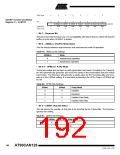
USART1 Control and Status
Register C – UCSR1C
7
–
6
UMSEL1
R/W
5
UPM11
R/W
0
4
UPM10
R/W
0
3
USBS1
R/W
0
UCSZ11 UCSZ10 UCPO1L
UCSR1C
Read/Write
Initial Value
R
0
R/W
1
R/W
1
R/W
0
0
• Bit 7 – Reserved Bit
This bit is reserved for future use. For compatibility with future devices, these bit must be
written to zero when UCSRnC is written.
• Bit 6 – UMSELn: USARTn Mode Select
This bit selects between asynchronous and synchronous mode of operation.
Table 79. UMSELn Bit Settings
UMSELn
Mode
0
1
Asynchronous Operation
Synchronous Operation
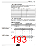
• Bit 5:4 – UPMn1:0: Parity Mode
These bits enable and set type of parity generation and check. If enabled, the Transmit-
ter will automatically generate and send the parity of the transmitted data bits within
each frame. The Receiver will generate a parity value for the incoming data and com-
pare it to the UPMn0 setting. If a mismatch is detected, the UPEn Flag in UCSRnA will
be set.
Table 80. UPMn Bits Settings
UPMn1
UPMn0
Parity Mode
0
0
1
1
0
1
0
1
Disabled
Reserved
Enabled, Even Parity
Enabled, Odd Parity
• Bit 3 – USBSn: Stop Bit Select
This bit selects the number of stop bits to be inserted by the Transmitter. The Receiver
ignores this setting.
Table 81. USBSn Bit Settings
USBSn
Stop Bit(s)
1-bit
0
1
2-bit
192
AT90CAN128
4250E–CAN–12/04

 ATMEL [ ATMEL ]