AT90CAN128
Note:
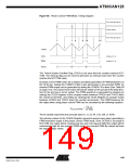
1. A special case occurs when OCR2A equals TOP and COM2A1 is set. In this case,
the compare match is ignored, but the set or clear is done at TOP. See “Fast PWM
Mode” on page 147 for more details.
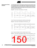
Table 69 shows the COM21:0 bit functionality when the WGM21:0 bits are set to phase
correct PWM mode.
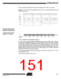
Table 69. Compare Output Mode, Phase Correct PWM Mode(1)
COM2A1
COM2A0
Description
0
0
1
0
1
0
Normal port operation, OC2A disconnected.
Reserved
Clear OC2A on compare match when up-counting.
Set OC2A on compare match when downcounting.
1
1
Set OC2A on compare match when up-counting.
Clear OC2A on compare match when downcounting.
Note:
1. A special case occurs when OCR2A equals TOP and COM2A1 is set. In this case,
the compare match is ignored, but the set or clear is done at TOP. See “Phase Cor-
rect PWM Mode” on page 148 for more details.
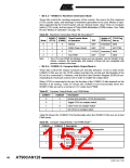
• Bit 2:0 – CS22:0: Clock Select
The three Clock Select bits select the clock source to be used by the Timer/Counter, see
Table 70.
Table 70. Clock Select Bit Description
CS22
CS21
CS20
Description
0
0
0
0
1
1
1
1
0
0
1
1
0
0
1
1
0
1
0
1
0
1
0
1
No clock source (Timer/Counter stopped).
clkT2S/(No prescaling)
clkT2S/8 (From prescaler)
clkT2S/32 (From prescaler)
clkT2S/64 (From prescaler)
clkT2S/128 (From prescaler)
clkT S/256 (From prescaler)
2
clkT S/1024 (From prescaler)
2
Timer/Counter2 Register –
TCNT2
Bit
7
6
5
4
3
2
1
0
TCNT2[7:0]
TCNT2
Read/Write
Initial Value
R/W
0
R/W
0
R/W
0
R/W
0
R/W
0
R/W
0
R/W
0
R/W
0
The Timer/Counter Register gives direct access, both for read and write operations, to
the Timer/Counter unit 8-bit counter. Writing to the TCNT2 Register blocks (removes)
the compare match on the following timer clock. Modifying the counter (TCNT2) while
the counter is running, introduces a risk of missing a compare match between TCNT2
and the OCR2A Register.
153
4250E–CAN–12/04

 ATMEL [ ATMEL ]