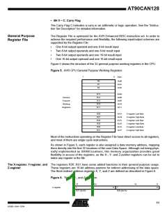
15
YH
YL
ZL
0
0
Y-register
Z-register
7
0
7
R29 (0x1D)
R28 (0x1C)
15
ZH
0
0
7
7
0
R31 (0x1F)
R30 (0x1E)
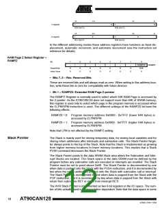
In the different addressing modes these address registers have functions as fixed dis-
placement, automatic increment, and automatic decrement (see the instruction set
reference for details).
RAM Page Z Select Register –
RAMPZ
Bit
7
–
6
–
5
–
4
–
3
–
2
–
1
–
0
RAMPZ0
R/W
RAMPZ
Read/Write
Initial Value
R
0
R
0
R
0
R
0
R
0
R
0
R
0
0
• Bits 7..2 – Res: Reserved Bits
These are reserved bits and will always read as zero. When writing to this address loca-
tion, write these bits to zero for compatibility with future devices.
• Bit 1 – RAMPZ0: Extended RAM Page Z-pointer
The RAMPZ Register is normally used to select which 64K RAM Page is accessed by
the Z-pointer. As the AT90CAN128 does not support more than 64K of SRAM memory,
this register is used only to select which page in the program memory is accessed when
the ELPM/SPM instruction is used. The different settings of the RAMPZ0 bit have the
following effects:
RAMPZ0 = 0: Program memory address 0x0000 - 0x7FFF (lower 64K bytes) is
accessed by ELPM/SPM
RAMPZ0 = 1: Program memory address 0x8000 - 0xFFFF (higher 64K bytes) is
accessed by ELPM/SPM
Note that LPM is not affected by the RAMPZ setting.
Stack Pointer
The Stack is mainly used for storing temporary data, for storing local variables and for
storing return addresses after interrupts and subroutine calls. The Stack Pointer Regis-
ter always points to the top of the Stack. Note that the Stack is implemented as growing
from higher memory locations to lower memory locations. This implies that a Stack
PUSH command decreases the Stack Pointer.
The Stack Pointer points to the data SRAM Stack area where the Subroutine and Inter-
rupt Stacks are located. This Stack space in the data SRAM must be defined by the
program before any subroutine calls are executed or interrupts are enabled. The Stack
Pointer must be set to point above 0x60. The Stack Pointer is decremented by one
when data is pushed onto the Stack with the PUSH instruction, and it is decremented by
two when the return address is pushed onto the Stack with subroutine call or interrupt.
The Stack Pointer is incremented by one when data is popped from the Stack with the
POP instruction, and it is incremented by two when data is popped from the Stack with
return from subroutine RET or return from interrupt RETI.
The AVR Stack Pointer is implemented as two 8-bit registers in the I/O space. The num-
ber of bits actually used is implementation dependent. Note that the data space in some
12
AT90CAN128
4250E–CAN–12/04

 ATMEL [ ATMEL ]