ATmega64A
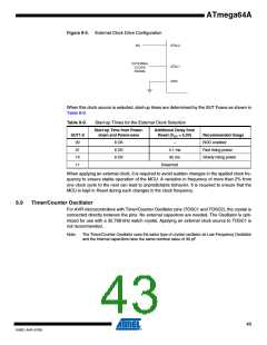
Figure 8-5. External Clock Drive Configuration
EXTERNAL
CLOCK
SIGNAL
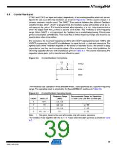
When this clock source is selected, start-up times are determined by the SUT Fuses as shown in
Table 8-9.
Table 8-9.
Start-up Times for the External Clock Selection
Start-up Time from Power-
down and Power-save
Additional Delay from
Reset (VCC = 5.0V)
SUT1:0
00
Recommended Usage
BOD enabled
6 CK
6 CK
6 CK
–
4.1 ms
01
Fast rising power
Slowly rising power
10
65 ms
11
Reserved
When applying an external clock, it is required to avoid sudden changes in the applied clock fre-
quency to ensure stable operation of the MCU. A variation in frequency of more than 2% from
one clock cycle to the next can lead to unpredictable behavior. It is required to ensure that the
MCU is kept in Reset during such changes in the clock frequency.
8.9
Timer/Counter Oscillator
For AVR microcontrollers with Timer/Counter Oscillator pins (TOSC1 and TOSC2), the crystal is
connected directly between the pins. No external capacitors are needed. The Oscillator is opti-
mized for use with a 32.768 kHz watch crystal. Applying an external clock source to TOSC1 is
not recommended.
Note:
The Timer/Counter Oscillator uses the same type of crystal oscillator as Low-Frequency Oscillator
and the internal capacitors have the same nominal value of 36 pF.
43
8160C–AVR–07/09

 ATMEL [ ATMEL ]