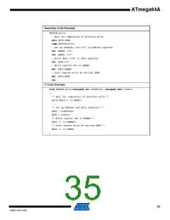
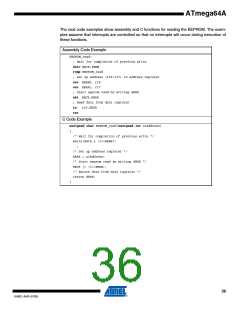
ATmega64A
8.4
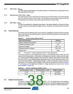
Crystal Oscillator
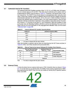
XTAL1 and XTAL2 are input and output, respectively, of an inverting amplifier which can be con-
figured for use as an On-chip Oscillator, as shown in Figure 8-2. Either a quartz crystal or a
ceramic resonator may be used. The CKOPT Fuse selects between two different Oscillator
amplifier modes. When CKOPT is programmed, the Oscillator output will oscillate a full rail-to-
rail swing on the output. This mode is suitable when operating in a very noisy environment or
when the output from XTAL2 drives a second clock buffer. This mode has a wide frequency
range. When CKOPT is unprogrammed, the Oscillator has a smaller output swing. This reduces
power consumption considerably. This mode has a limited frequency range and it cannot be
used to drive other clock buffers.
For resonators, the maximum frequency is 8 MHz with CKOPT unprogrammed and 16 MHz with
CKOPT programmed. C1 and C2 should always be equal for both crystals and resonators. The
optimal value of the capacitors depends on the crystal or resonator in use, the amount of stray
capacitance, and the electromagnetic noise of the environment. Some initial guidelines for
choosing capacitors for use with crystals are given in Table 8-3. For ceramic resonators, the
capacitor values given by the manufacturer should be used.
Figure 8-2. Crystal Oscillator Connections
C2
XTAL2
C1
XTAL1
GND
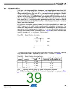
The Oscillator can operate in three different modes, each optimized for a specific frequency
range. The operating mode is selected by the fuses CKSEL3:1 as shown in Table 8-3.
Figure 8-3. Crystal Oscillator Operating Modes
Frequency Range
(MHz)
Recommended Range for Capacitors
C1 and C2 for Use with Crystals (pF)
CKOPT
CKSEL3:1
101(1)
1
1
1
0
0.4 - 0.9
0.9 - 3.0
3.0 - 8.0
1.0 -
–
110
12 - 22
12 - 22
12 - 22
111
101, 110, 111
Note:
1. This option should not be used with crystals, only with ceramic resonators.
The CKSEL0 Fuse together with the SUT1:0 Fuses select the start-up times as shown in Table
8-3.
39
8160C–AVR–07/09

 ATMEL [ ATMEL ]