ATmega64A
8.1.3
8.1.4
Flash Clock – clkFLASH
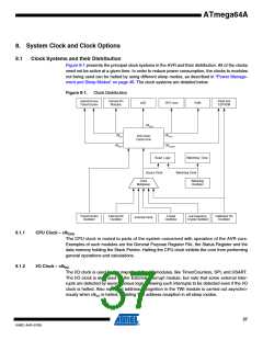
The Flash clock controls operation of the Flash interface. The Flash clock is usually active simul-
taneously with the CPU clock.
Asynchronous Timer Clock – clkASY
The Asynchronous Timer clock allows the Asynchronous Timer/Counter to be clocked directly
from an external 32 kHz clock crystal. The dedicated clock domain allows using this
Timer/Counter as a real-time counter even when the device is in sleep mode.
8.1.5
ADC Clock – clkADC
The ADC is provided with a dedicated clock domain. This allows halting the CPU and I/O clocks
in order to reduce noise generated by digital circuitry. This gives more accurate ADC conversion
results.
8.2
Clock Sources
The device has the following clock source options, selectable by Flash Fuse bits as shown
below. The clock from the selected source is input to the AVR clock generator, and routed to the
appropriate modules.
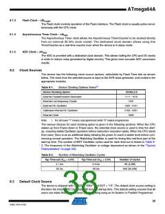
Table 8-1.
Device Clocking Options Select(1)
Device Clocking Option
External Crystal/Ceramic Resonator
External Low-frequency Crystal
External RC Oscillator
CKSEL3:0
1111 - 1010
1001
1000 - 0101
0100 - 0001
0000
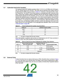
Calibrated Internal RC Oscillator
External Clock
Note:
1. For all fuses “1” means unprogrammed while “0” means programmed.
The various choices for each clocking option is given in the following sections. When the CPU
wakes up from Power-down or Power-save, the selected clock source is used to time the start-
up, ensuring stable Oscillator operation before instruction execution starts. When the CPU starts
from reset, there is as an additional delay allowing the power to reach a stable level before com-
mencing normal operation. The Watchdog Oscillator is used for timing this real-time part of the
start-up time. The number of WDT Oscillator cycles used for each time-out is shown in Table 8-
2. The frequency of the Watchdog Oscillator is voltage dependent as shown in the “Typical
Characteristics” on page 343.
Table 8-2.
Number of Watchdog Oscillator Cycles
Typ Time-out (VCC = 5.0V)
Typ Time-out (VCC = 3.0V)
Number of Cycles
4K (4,096)
4.1 ms
65 ms
4.3 ms
69 ms
64K (65,536)
8.3
Default Clock Source
The device is shipped with CKSEL = “0001” and SUT = “10”. The default clock source setting is
therefore the Internal RC Oscillator with longest startup time. This default setting ensures that all
users can make their desired clock source setting using an In-System or Parallel Programmer.
38
8160C–AVR–07/09

 ATMEL [ ATMEL ]