ATmega64A
Note:
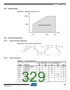
1. Refer to “External Clock” on page 42 for details.
Table 28-2. External RC Oscillator, Typical Frequencies
R [kΩ](1)
31.5
C [pF]
20
f(2)
650 kHz
2.0 MHz
6.5
20
Note:
1. R should be in the range 3kΩ - 100kΩ, and C should be at least 20 pF. The C values given in
the table includes pin capacitance. This will vary with package type.
2. The frequency will vary with package type and board layout.
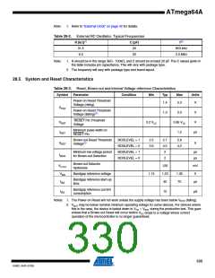
28.5 System and Reset Characteristics
Table 28-3. Reset, Brown-out and internal Voltage reference Characteristics
Symbol
Parameter
Condition
Min
Typ
Max
Units
Power-on Reset Threshold
Voltage (rising)
1.4
2.3
V
VPOT
Power-on Reset Threshold
Voltage (falling)(1)
1.3
2.3
0.85 VCC
1.5
V
V
RESET Pin Threshold
Voltage
VRST
tRST
0.2 VCC
Minimum pulse width on
RESET Pin
µs
Brown-out Reset Threshold
Voltage(2)
BODLEVEL = 1
BODLEVEL = 0
BODLEVEL = 1
BODLEVEL = 0
2.5
3.6
2.7
4.0
2
2.9
4.2
VBOT
V
Minimum low voltage period
for Brown-out Detection
µs
µs
tBOD
2
Brown-out Detector
hysteresis
VHYST
VBG
tBG
120
1.23
40
mV
V
Bandgap reference voltage
1.15
1.35
70
Bandgap reference start-up
time
µs
Bandgap reference current
consumption
IBG
10
µA
Notes: 1. The Power-on Reset will not work unless the supply voltage has been below VPOT (falling).
2. VBOT may be below nominal minimum operating voltage for some devices. For devices where
this is the case, the device is tested down to VCC = VBOT during the production test. This guar-
antees that a Brown-out Reset will occur before VCC drops to a voltage where correct
operation of the microcontroller is no longer guaranteed.
330
8160C–AVR–07/09

 ATMEL [ ATMEL ]