ATmega64A
28.3 Speed Grades
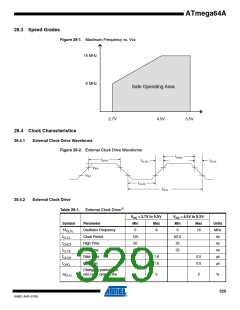
Figure 28-1. Maximum Frequency vs. Vcc
16 MHz
8 MHz
Safe Operating Area
2.7V
4.5V
5.5V
28.4 Clock Characteristics
28.4.1
External Clock Drive Waveforms
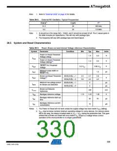
Figure 28-2. External Clock Drive Waveforms
V
IH1
V
IL1
28.4.2
External Clock Drive
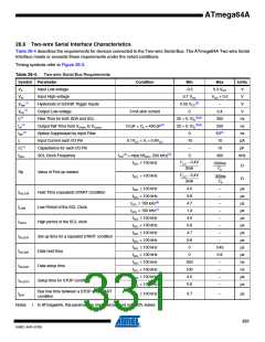
Table 28-1. External Clock Drive(1)
VCC = 2.7V to 5.5V
VCC = 4.5V to 5.5V
Symbol
1/tCLCL
tCLCL
Parameter
Oscillator Frequency
Clock Period
High Time
Min Max
Min
0
Max
Units
MHz
ns
0
8
16
125
50
62.5
25
tCHCX
tCLCX
ns
Low Time
50
25
ns
tCLCH
Rise Time
1.6
1.6
0.5
0.5
μs
tCHCL
Fall Time
μs
Change in period from
one clock cycle to the
next
ΔtCLCL
2
2
%
329
8160C–AVR–07/09

 ATMEL [ ATMEL ]