ATmega64A
26. Boot Loader Support – Read-While-Write Self-programming
26.1 Features
• Read-While-Write Self-programming
• Flexible Boot Memory Size
• High Security (Separate Boot Lock Bits for a Flexible Protection)
• Separate Fuse to Select Reset Vector
• Optimized Page(1) Size
• Code Efficient Algorithm
• Efficient Read-Modify-Write Support
Note:
1. A page is a section in the Flash consisting of several bytes (see Table 27-9 on page 300) used
during programming. The page organization does not affect normal operation.
26.2 Overview
The Boot Loader Support provides a real Read-While-Write Self-programming mechanism for
downloading and uploading program code by the MCU itself. This feature allows flexible applica-
tion software updates controlled by the MCU using a Flash-resident Boot Loader program. The
Boot Loader program can use any available data interface and associated protocol to read code
and write (program) that code into the Flash memory, or read the code from the program mem-
ory. The program code within the Boot Loader section has the capability to write into the entire
Flash, including the Boot Loader Memory. The Boot Loader can thus even modify itself, and it
can also erase itself from the code if the feature is not needed anymore. The size of the Boot
Loader Memory is configurable with Fuses and the Boot Loader has two separate sets of Boot
Lock bits which can be set independently. This gives the user a unique flexibility to select differ-
ent levels of protection.
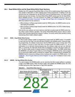
26.3 Application and Boot Loader Flash Sections
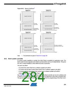
The Flash memory is organized in two main sections, the Application section and the Boot
Loader section (see Figure 26-2). The size of the different sections is configured by the
BOOTSZ Fuses as shown in Table 26-6 on page 292 and Figure 26-2. These two sections can
have different levels of protection since they have different sets of Lock bits.
26.3.1
26.3.2
Application Section
The Application section is the section of the Flash that is used for storing the application code.
The protection level for the Application section can be selected by the application Boot Lock bits
(Boot Lock bits 0), see Table 26-2 on page 285. The Application section can never store any
Boot Loader code since the SPM instruction is disabled when executed from the Application
section.
BLS – Boot Loader Section
While the Application section is used for storing the application code, the Boot Loader software
must be located in the BLS since the SPM instruction can initiate a programming when execut-
ing from the BLS only. The SPM instruction can access the entire Flash, including the BLS itself.
The protection level for the Boot Loader section can be selected by the Boot Loader Lock bits
(Boot Lock bits 1), see Table 26-3 on page 285.
281
8160C–AVR–07/09

 ATMEL [ ATMEL ]