ATmega64A
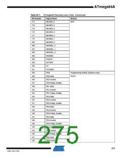
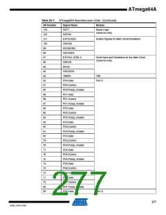
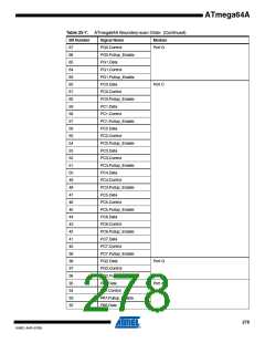
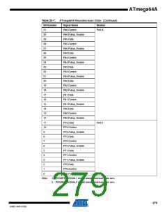
Table 25-7. ATmega64A Boundary-scan Order (Continued)
Bit Number
Signal Name
PA6.Control
Module
31
30
29
28
27
26
25
24
23
22
21
20
19
18
17
16
15
14
13
12
11
10
9
Port A
PA6.Pullup_Enable
PA5.Data
PA5.Control
PA5.Pullup_Enable
PA4.Data
PA4.Control
PA4.Pullup_Enable
PA3.Data
PA3.Control
PA3.Pullup_Enable
PA2.Data
PA2.Control
PA2.Pullup_Enable
PA1.Data
PA1.Control
PA1.Pullup_Enable
PA0.Data
PA0.Control
PA0.Pullup_Enable
PF3.Data
Port F
PF3.Control
PF3.Pullup_Enable
PF2.Data
8
7
PF2.Control
6
PF2.Pullup_Enable
PF1.Data
5
4
PF1.Control
3
PF1.Pullup_Enable
PF0.Data
2
1
PF0.Control
0
PF0.Pullup_Enable
Note:
1. PRIVATE_SIGNAL1 should always scanned in as zero.
2. PRIVATE_SIGNAL2 should always scanned in as zero.
279
8160C–AVR–07/09

 ATMEL [ ATMEL ]