ATmega64A
25.7 Boundary-scan Description Language Files
Boundary-scan Description Language (BSDL) files describe Boundary-scan capable devices in
a standard format used by automated test-generation software. The order and function of bits in
the Boundary-scan Data Register are included in this description.
25.8 Boundary-scan Related Register in I/O Memory
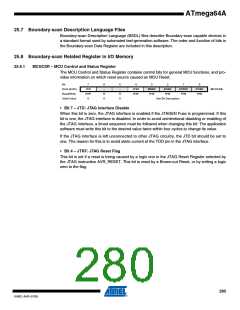
25.8.1
MCUCSR – MCU Control and Status Register
The MCU Control and Status Register contains control bits for general MCU functions, and pro-
vides information on which reset source caused an MCU Reset.
Bit
7
6
–
5
–
4
3
2
BORF
1
0
0x34 (0x54)
Read/Write
Initial Value
JTD
R/W
0
JTRF
R/W
WDRF
R/W
EXTRF
R/W
PORF
R/W
MCUCSR
R
0
R
0
R/W
See Bit Description
• Bit 7 – JTD: JTAG Interface Disable
When this bit is zero, the JTAG interface is enabled if the JTAGEN Fuse is programmed. If this
bit is one, the JTAG interface is disabled. In order to avoid unintentional disabling or enabling of
the JTAG interface, a timed sequence must be followed when changing this bit: The application
software must write this bit to the desired value twice within four cycles to change its value.
If the JTAG interface is left unconnected to other JTAG circuitry, the JTD bit should be set to
one. The reason for this is to avoid static current at the TDO pin in the JTAG interface.
• Bit 4 – JTRF: JTAG Reset Flag
This bit is set if a reset is being caused by a logic one in the JTAG Reset Register selected by
the JTAG instruction AVR_RESET. This bit is reset by a Brown-out Reset, or by writing a logic
zero to the flag.
280
8160C–AVR–07/09

 ATMEL [ ATMEL ]