ATmega64A
• Bit 0 – TWIE: TWI Interrupt Enable
When this bit is written to one, and the I-bit in SREG is set, the TWI interrupt request will be acti-
vated for as long as the TWINT flag is high.
21.9.3
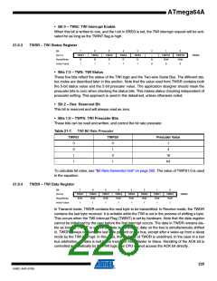
TWSR – TWI Status Register
Bit
7
TWS7
R
6
TWS6
R
5
TWS5
R
4
TWS4
R
3
TWS3
R
2
–
1
TWPS1
R/W
0
0
TWPS0
R/W
0
(0x71)
TWSR
Read/Write
Initial Value
R
0
1
1
1
1
1
• Bits 7:3 – TWS: TWI Status
These five bits reflect the status of the TWI logic and the Two-wire Serial Bus. The different sta-
tus codes are described later in this section. Note that the value read from TWSR contains both
the 5-bit status value and the 2-bit prescaler value. The application designer should mask the
prescaler bits to zero when checking the status bits. This makes status checking independent of
prescaler setting. This approach is used in this datasheet, unless otherwise noted.
• Bit 2 – Res: Reserved Bit
This bit is reserved and will always read as zero.
• Bits 1:0 – TWPS: TWI Prescaler Bits
These bits can be read and written, and control the bit rate prescaler.
Table 21-7. TWI Bit Rate Prescaler
TWPS1
TWPS0
Prescaler Value
0
0
1
1
0
1
0
1
1
4
16
64
To calculate bit rates, see “Bit Rate Generator Unit” on page 202. The value of TWPS1:0 is used
in the equation.
21.9.4
TWDR – TWI Data Register
Bit
7
TWD7
R/W
1
6
TWD6
R/W
1
5
TWD5
R/W
1
4
TWD4
R/W
1
3
TWD3
R/W
1
2
TWD2
R/W
1
1
TWD1
R/W
1
0
TWD0
R/W
1
(0x73)
TWDR
Read/Write
Initial Value
In Transmit mode, TWDR contains the next byte to be transmitted. In Receive mode, the TWDR
contains the last byte received. It is writable while the TWI is not in the process of shifting a byte.
This occurs when the TWI Interrupt Flag (TWINT) is set by hardware. Note that the data register
cannot be initialized by the user before the first interrupt occurs. The data in TWDR remains sta-
ble as long as TWINT is set. While data is shifted out, data on the bus is simultaneously shifted
in. TWDR always contains the last byte present on the bus, except after a wake-up from a sleep
mode by the TWI interrupt. In this case, the contents of TWDR is undefined. In the case of a lost
bus arbitration, no data is lost in the transition from Master to Slave. Handling of the ACK bit is
controlled automatically by the TWI logic, the CPU cannot access the ACK bit directly.
228
8160C–AVR–07/09

 ATMEL [ ATMEL ]