ATmega64A
Losing masters will switch to not addressed Slave mode or wait until the bus is free and
transmit a new START condition, depending on application software action.
• Two or more masters are accessing different slaves. In this case, arbitration will occur in the
SLA bits. Masters trying to output a one on SDA while another master outputs a zero will lose
the arbitration. Masters losing arbitration in SLA will switch to Slave mode to check if they are
being addressed by the winning master. If addressed, they will switch to SR or ST mode,
depending on the value of the READ/WRITE bit. If they are not being addressed, they will
switch to not addressed Slave mode or wait until the bus is free and transmit a new START
condition, depending on application software action.
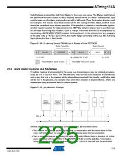
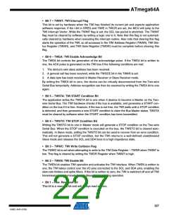
This is summarized in Figure 21-21. Possible status values are given in circles.
Figure 21-21. Possible Status Codes Caused by Arbitration
START
SLA
Data
STOP
Arbitration lost in SLA
Arbitration lost in Data
Own
No
38
TWI bus will be released and not addressed slave mode will be entered
A START condition will be transmitted when the bus becomes free
Address / General Call
received
Yes
Write
68/78
B0
Data byte will be received and NOT ACK will be returned
Data byte will be received and ACK will be returned
Direction
Read
Last data byte will be transmitted and NOT ACK should be received
Data byte will be transmitted and ACK should be received
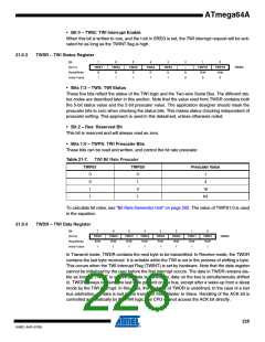
21.9 TWI Register Description
21.9.1
TWBR –TWI Bit Rate Register
Bit
7
6
TWBR6
R/W
0
5
TWBR5
R/W
0
4
TWBR4
R/W
0
3
2
TWBR2
R/W
0
1
TWBR1
R/W
0
0
TWBR0
R/W
0
(0x70)
TWBR7
R/W
0
TWBR3
R/W
0
TWBR
Read/Write
Initial Value
• Bits 7:0 – TWI Bit Rate Register
TWBR selects the division factor for the bit rate generator. The bit rate generator is a frequency
divider which generates the SCL clock frequency in the Master modes. See “Bit Rate Generator
Unit” on page 202 for calculating bit rates.
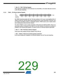
21.9.2
TWCR – TWI Control Register
Bit
7
TWINT
R/W
0
6
TWEA
R/W
0
5
TWSTA
R/W
0
4
TWSTO
R/W
0
3
2
TWEN
R/W
0
1
–
0
TWIE
R/W
0
(0x74)
TWWC
TWCR
Read/Write
Initial Value
R
0
R
0
The TWCR is used to control the operation of the TWI. It is used to enable the TWI, to initiate a
Master access by applying a START condition to the bus, to generate a Receiver acknowledge,
to generate a stop condition, and to control halting of the bus while the data to be written to the
bus are written to the TWDR. It also indicates a write collision if data is attempted written to
TWDR while the register is inaccessible.
226
8160C–AVR–07/09

 ATMEL [ ATMEL ]