ATmega64A
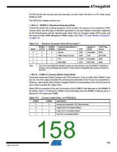
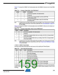
Table 17-4 shows the COM21:0 bit functionality when the WGM21:0 bits are set to fast PWM
mode.
Table 17-4. Compare Output Mode, Fast PWM Mode(1)
COM21
COM20
Description
0
0
1
0
1
0
Normal port operation, OC2 disconnected.
Reserved
Clear OC2 on Compare Match, set OC2 at BOTTOM,
(non-inverting mode).
1
1
Set OC2 on Compare Match, clear OC2 at BOTTOM,
(inverting mode).
Note:
1. A special case occurs when OCR2 equals TOP and COM21 is set. In this case, the Compare
Match is ignored, but the set or clear is done at BOTTOM. See “Fast PWM Mode” on page 152
for more details.
Table 17-5 shows the COM21:0 bit functionality when the WGM21:0 bits are set to phase cor-
rect PWM mode.
Table 17-5. Compare Output Mode, Phase Correct PWM Mode(1)
COM21
COM20
Description
0
0
1
0
1
0
Normal port operation, OC2 disconnected.
Reserved
Clear OC2 on Compare Match when up-counting. Set OC2 on Compare Match
when downcounting.
1
1
Set OC2 on Compare Match when up-counting. Clear OC2 on Compare Match
when downcounting.
Note:
1. A special case occurs when OCR2 equals TOP and COM21 is set. In this case, the Compare
Match is ignored, but the set or clear is done at TOP. See “Phase Correct PWM Mode” on page
154 for more details.
• Bit 2:0 – CS22:0: Clock Select
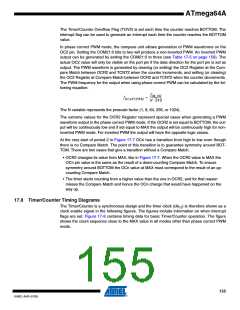
The three Clock Select bits select the clock source to be used by the Timer/Counter.
Table 17-6. Clock Select Bit Description
CS22
CS21
CS20
Description
0
0
0
0
1
1
1
1
0
0
1
1
0
0
1
1
0
1
0
1
0
1
0
1
No clock source (Timer/counter stopped).
clkI/O/(No prescaling)
clkI/O/8 (From prescaler)
clkI/O/64 (From prescaler)
clkI/O/256 (From prescaler)
clkI/O/1024 (From prescaler)
External clock source on T2 pin. Clock on falling edge.
External clock source on T2 pin. Clock on rising edge.
If external pin modes are used for the Timer/Counter2, transitions on the T2 pin will clock the
counter even if the pin is configured as an output. This feature allows software control of the
counting.
159
8160C–AVR–07/09

 ATMEL [ ATMEL ]