ACMPN2, Analog Comparator 2 Negative Input. Configure the port pin as input with the internal
pull-up switched off to avoid the digital port function from interfering with the function of the Ana-
log Comparator.
INT0, External Interrupt source 0. This pin can serve as an external interrupt source to the MCU.
PCINT22, Pin Change Interrupt 23.
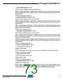
• ADC2/ACMP2/PCINT21 – Bit 5
ADC2, Analog to Digital Converter, input channel 2.
ACMP2, Analog Comparator 1 Positive Input. Configure the port pin as input with the internal
pull-up switched off to avoid the digital port function from interfering with the function of the Ana-
log Comparator.
PCINT21, Pin Change Interrupt 21.
• PCINT20/ADC1/RXD/RXLIN/ICP1/SCK_A – Bit 4
ADC1, Analog to Digital Converter, input channel 1.
RXD/RXLIN, LIN/UART Receive Pin. Receive Data (Data input pin for the LIN/UART). When the
LIN/UART receiver is enabled this pin is configured as an input regardless of the value of
DDRD4. When the UART forces this pin to be an input, a logical one in PORTD4 will turn on the
internal pull-up.
ICP1, Input Capture Pin1: This pin can act as an input capture pin for Timer/Counter1.
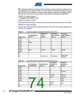
SCK_A: Master Clock output, Slave Clock input pin for SPI channel. When the SPI is enabled as
a slave, this pin is configured as an input regardless of the setting of DDD4. When the SPI is
enabled as a master, the data direction of this pin is controlled by DDD4. When the pin is forced
to be an input, the pull-up can still be controlled by the PORTD4 bit.
PCINT20, Pin Change Interrupt 20.
• PCINT19/TXD/TXLIN/OC0A/SS/MOSI_A, Bit 3
TXD/TXLIN, LIN/UART Transmit pin. Data output pin for the LIN/UART. When the LIN/UART
Transmitter is enabled, this pin is configured as an output regardless of the value of DDD3.
OC0A, Output Compare Match A output: This pin can serve as an external output for the
Timer/Counter0 Output Compare A. The pin has to be configured as an output (DDD3 set “one”)
to serve this function. The OC0A pin is also the output pin for the PWM mode
SS: Slave Port Select input. When the SPI is enabled as a slave, this pin is configured as an
input regardless of the setting of DDD3. As a slave, the SPI is activated when this pin is driven
low. When the SPI is enabled as a master, the data direction of this pin is controlled by DDD3.
When the pin is forced to be an input, the pull-up can still be controlled by the PORTD3 bit.
MOSI_A: SPI Master Data output, Slave Data input for SPI channel. When the SPI is enabled as
a slave, this pin is configured as an input regardless of the setting of DDD3 When the SPI is
enabled as a master, the data direction of this pin is controlled by DDD3. When the pin is forced
to be an input, the pull-up can still be controlled by the PORTD3 bit.
PCINT19, Pin Change Interrupt 19.
• PCINT18/PSCIN2/OC1A/MISO_A, Bit 2
PCSIN2, PSC Digital Input 2.
OC1A, Output Compare Match A output: This pin can serve as an external output for the
Timer/Counter1 Output Compare A. The pin has to be configured as an output (DDD2 set “one”)
to serve this function. The OC1A pin is also the output pin for the PWM mode timer function.
76
ATmega16/32/64/M1/C1
7647F–AVR–04/09

 ATMEL [ ATMEL ]