ATmega16/32/64/M1/C1
0x02E
0x030
0x032
0x034
0x036
0x038
0x03A
0x03C
;
jmp
jmp
jmp
jmp
jmp
jmp
jmp
jmp
PCINT1
PCINT2
PCINT3
SPI_STC
ADC
; Pin Change Int Request 1 Handler
; Pin Change Int Request 2 Handler
; Pin Change Int Request 3 Handler
; SPI Transfer Complete Handler
; ADC Conversion Complete Handler
; Watchdog Timer Handler
WDT
EE_RDY
SPM_RDY
; EEPROM Ready Handler
; Store Program Memory Ready Handler
0x03ERESET:
0x03F
0x040
ldi
out
ldi
r16, high(RAMEND); Main program start
SPH,r16
; Set Stack Pointer to top of RAM
r16, low(RAMEND)
0x041
0x042
out
sei
<instr> xxx
... ... ...
SPL,r16
; Enable interrupts
0x043
...
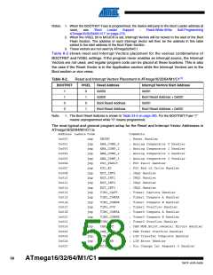
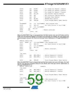
When the BOOTRST Fuse is unprogrammed, the Boot section size set to 2K bytes and the
IVSEL bit in the MCUCR Register is set before any interrupts are enabled, the most typical and
general program setup for the Reset and Interrupt Vector Addresses in ATmega16/32/64/M1/C1
is:
Address Labels Code
Comments
0x000
0x001
0x002
RESET: ldi
out
r16,high(RAMEND); Main program start
SPH,r16
; Set Stack Pointer to top of RAM
ldi
r16,low(RAMEND)
SPL,r16
0x003
0x004
out
sei
; Enable interrupts
0x005
;
<instr> xxx
.org 0xC02
0xC02
jmp
jmp
...
jmp
ANA_COMP_0
ANA_COMP_1
...
; Analog Comparator 0 Handler
; Analog Comparator 1 Handler
;
0xC04
...
0xC3C
SPM_RDY
; Store Program Memory Ready Handler
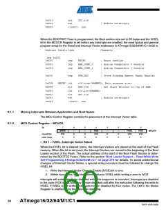
When the BOOTRST Fuse is programmed and the Boot section size set to 2K bytes, the most
typical and general program setup for the Reset and Interrupt Vector Addresses in
ATmega16/32/64/M1/C1 is:
Address Labels Code
Comments
.org 0x002
0x002
0x004
...
jmp
jmp
...
jmp
ANA_COMP_0
ANA_COMP_1
...
; Analog Comparator 0 Handler
; Analog Comparator 1 Handler
;
0x03C
;
SPM_RDY
; Store Program Memory Ready Handler
.org 0xC00
0xC00
0xC01
0xC02
RESET: ldi
r16,high(RAMEND); Main program start
out
SPH,r16
; Set Stack Pointer to top of RAM
ldi
r16,low(RAMEND)
59
7647F–AVR–04/09

 ATMEL [ ATMEL ]