0xC03
0xC04
out
sei
SPL,r16
; Enable interrupts
0xC05
<instr> xxx
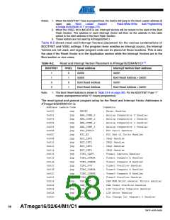
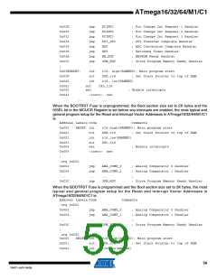
When the BOOTRST Fuse is programmed, the Boot section size set to 2K bytes and the IVSEL
bit in the MCUCR Register is set before any interrupts are enabled, the most typical and general
program setup for the Reset and Interrupt Vector Addresses in ATmega16/32/64/M1/C116/32 is:
Address Labels Code
Comments
;
.org 0xC00
0xC00
0xC02
0xC04
...
jmp
jmp
jmp
...
jmp
RESET
; Reset handler
ANA_COMP_0
ANA_COMP_1
...
; Analog Comparator 0 Handler
; Analog Comparator 1 Handler
;
0xC3C
;
SPM_RDY
; Store Program Memory Ready Handler
0xC3E
0xC3F
0xC40
RESET: ldi
out
r16,high(RAMEND); Main program start
SPH,r16
; Set Stack Pointer to top of RAM
ldi
r16,low(RAMEND)
SPL,r16
0xC41
0xC42
out
sei
; Enable interrupts
0xC43
<instr> xxx
8.1.1
8.1.2
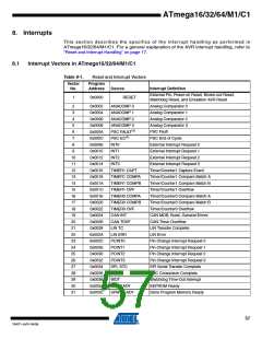
Moving Interrupts Between Application and Boot Space
The MCU Control Register controls the placement of the Interrupt Vector table.
MCU Control Register – MCUCR
Bit
7
6
–
5
–
4
3
–
2
–
1
IVSEL
R/W
0
0
IVCE
R/W
0
SPIPS
R/W
0
PUD
R/W
0
MCUCR
Read/Write
Initial Value
R
0
R
0
R
0
R
0
• Bit 1 – IVSEL: Interrupt Vector Select
When the IVSEL bit is cleared (zero), the Interrupt Vectors are placed at the start of the Flash
memory. When this bit is set (one), the Interrupt Vectors are moved to the beginning of the Boot
Loader section of the Flash. The actual address of the start of the Boot Flash Section is deter-
mined by the BOOTSZ Fuses. Refer to the section “Boot Loader Support – Read-While-Write
Self-Programming ATmega16/32/64/M1/C1” on page 279 for details. To avoid unintentional
changes of Interrupt Vector tables, a special write procedure must be followed to change the
IVSEL bit:
1. Write the Interrupt Vector Change Enable (IVCE) bit to one.
2. Within four cycles, write the desired value to IVSEL while writing a zero to IVCE.
Interrupts will automatically be disabled while this sequence is executed. Interrupts are disabled
in the cycle IVCE is set, and they remain disabled until after the instruction following the write to
IVSEL. If IVSEL is not written, interrupts remain disabled for four cycles. The I-bit in the Status
Register is unaffected by the automatic disabling.
60
ATmega16/32/64/M1/C1
7647F–AVR–04/09

 ATMEL [ ATMEL ]