ATmega16/32/64/M1/C1
7.4.1
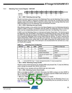
Watchdog Timer Control Register - WDTCSR
Bit
7
WDIF
R/W
0
6
WDIE
R/W
0
5
WDP3
R/W
0
4
WDCE
R/W
0
3
WDE
R/W
X
2
WDP2
R/W
0
1
WDP1
R/W
0
0
WDP0
R/W
0
WDTCSR
Read/Write
Initial Value
• Bit 7 - WDIF: Watchdog Interrupt Flag
This bit is set when a time-out occurs in the Watchdog Timer and the Watchdog Timer is config-
ured for interrupt. WDIF is cleared by hardware when executing the corresponding interrupt
handling vector. Alternatively, WDIF is cleared by writing a logic one to the flag. When the I-bit in
SREG and WDIE are set, the Watchdog Time-out Interrupt is executed.
• Bit 6 - WDIE: Watchdog Interrupt Enable
When this bit is written to one and the I-bit in the Status Register is set, the Watchdog Interrupt is
enabled. If WDE is cleared in combination with this setting, the Watchdog Timer is in Interrupt
Mode, and the corresponding interrupt is executed if time-out in the Watchdog Timer occurs.
If WDE is set, the Watchdog Timer is in Interrupt and System Reset Mode. The first time-out in
the Watchdog Timer will set WDIF. Executing the corresponding interrupt vector will clear WDIE
and WDIF automatically by hardware (the Watchdog goes to System Reset Mode). This is use-
ful for keeping the Watchdog Timer security while using the interrupt. To stay in Interrupt and
System Reset Mode, WDIE must be set after each interrupt. This should however not be done
within the interrupt service routine itself, as this might compromise the safety-function of the
Watchdog System Reset mode. If the interrupt is not executed before the next time-out, a Sys-
tem Reset will be applied.
Table 7-5.
Watchdog Timer Configuration
WDTON(1)
WDE
WDIE
Mode
Action on Time-out
None
0
0
0
0
0
1
0
1
0
Stopped
Interrupt Mode
System Reset Mode
Interrupt
Reset
Interrupt and System Reset
Mode
Interrupt, then go to System
Reset Mode
0
1
1
x
1
x
System Reset Mode
Reset
Note:
1. For the WDTON Fuse “1” means unprogrammed while “0” means programmed.
• Bit 4 - WDCE: Watchdog Change Enable
This bit is used in timed sequences for changing WDE and prescaler bits. To clear the WDE bit,
and/or change the prescaler bits, WDCE must be set.
Once written to one, hardware will clear WDCE after four clock cycles.
• Bit 3 - WDE: Watchdog System Reset Enable
WDE is overridden by WDRF in MCUSR. This means that WDE is always set when WDRF is
set. To clear WDE, WDRF must be cleared first. This feature ensures multiple resets during con-
ditions causing failure, and a safe start-up after the failure.
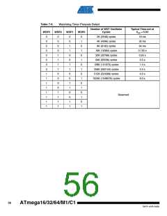
• Bit 5, 2..0 - WDP3..0: Watchdog Timer Prescaler 3, 2, 1 and 0
The WDP3..0 bits determine the Watchdog Timer prescaling when the Watchdog Timer is run-
ning. The different prescaling values and their corresponding time-out periods are shown in
Table 7-6 on page 56.
55
7647F–AVR–04/09

 ATMEL [ ATMEL ]