ATmega16/32/64/M1/C1
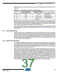
When this clock source is selected, start-up times are determined by the SUT Fuses as shown in
Table 5-9.
Table 5-9.
Start-up Times for the External Clock Selection
Start-up Time from
Power-down and Power-save
Additional Delay from
Reset (VCC = 5.0V)
SUT1..0
00
Recommended Usage
BOD enabled
6 CK
6 CK
6 CK
14CK
01
14CK + 4.1 ms
14CK + 65 ms
Reserved
Fast rising power
Slowly rising power
10
11
When applying an external clock, it is required to avoid sudden changes in the applied clock fre-
quency to ensure stable operation of the MCU. A variation in frequency of more than 2% from
one clock cycle to the next can lead to unpredictable behavior. It is required to ensure that the
MCU is kept in Reset during such changes in the clock frequency.
Note that the System Clock Prescaler can be used to implement run-time changes of the internal
clock frequency while still ensuring stable operation. Refer to “System Clock Prescaler” on page
37 for details.
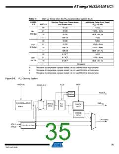
5.9
Clock Output Buffer
When the CKOUT Fuse is programmed, the system Clock will be output on CLKO. This mode is
suitable when chip clock is used to drive other circuits on the system. The clock will be output
also during reset and the normal operation of I/O pin will be overridden when the fuse is pro-
grammed. Any clock source, including internal RC Oscillator, can be selected when CLKO
serves as clock output. If the System Clock Prescaler is used, it is the divided system clock that
is output (CKOUT Fuse programmed).
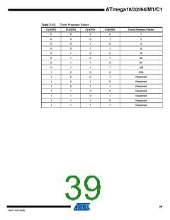
5.10 System Clock Prescaler
The ATmega16/32/64/M1/C1 system clock can be divided by setting the Clock Prescale Regis-
ter – CLKPR. This feature can be used to decrease power consumption when the requirement
for processing power is low. This can be used with all clock source options, and it will affect the
clock frequency of the CPU and all synchronous peripherals. clkI/O, clkADC, clkCPU, and clkFLASH
are divided by a factor as shown in Table 5-10.
When switching between prescaler settings, the System Clock Prescaler ensures that no
glitches occurs in the clock system. It also ensures that no intermediate frequency is higher than
neither the clock frequency corresponding to the previous setting, nor the clock frequency corre-
sponding to the new setting. The ripple counter that implements the prescaler runs at the
frequency of the undivided clock, which may be faster than the CPU's clock frequency. Hence, it
is not possible to determine the state of the prescaler - even if it were readable, and the exact
time it takes to switch from one clock division to the other cannot be exactly predicted. From the
time the CLKPS values are written, it takes between T1 + T2 and T1 + 2 * T2 before the new
clock frequency is active. In this interval, 2 active clock edges are produced. Here, T1 is the pre-
vious clock period, and T2 is the period corresponding to the new prescaler setting.
37
7647F–AVR–04/09

 ATMEL [ ATMEL ]