ATmega16/32/64/M1/C1
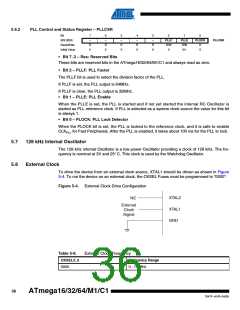
Table 5-7.
Start-up Times when the PLL is selected as system clock
CKSEL
3..0
Start-up Time from Power-down
and Power-save
Additional Delay from Reset
(VCC = 5.0V)
SUT1..0
00
1K CK
1K CK
1K CK
16K CK
1K CK
1K CK
16K CK
16K CK
6 CK (1)
6 CK (2)
6 CK (3)
14CK
01
14CK + 4 ms
14CK + 64 ms
14CK
0011
RC Osc
10
11
00
14CK
01
14CK + 4 ms
14CK + 4 ms
14CK + 64 ms
14CK
0101
Ext Osc
10
11
00
01
14CK + 4 ms
14CK + 64 ms
0001
Ext Clk
10
11
Reserved
1.
2.
3.
This value do not provide a proper restart ; do not use PD in this clock scheme
This value do not provide a proper restart ; do not use PD in this clock scheme
This value do not provide a proper restart ; do not use PD in this clock scheme
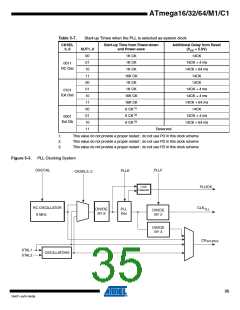
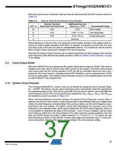
Figure 5-3. PLL Clocking System
OSCCAL
PLLF
PLLE
CKSEL3..0
Lock
Detector
PLOCK
CLKPLL
RC OSCILLATOR
8 MHz
DIVIDE
BY 8
PLL
64x
DIVIDE
BY 2
DIVIDE
BY 4
CKSOURCE
XTAL1
XTAL2
OSCILLATORS
35
7647F–AVR–04/09

 ATMEL [ ATMEL ]