ATmega16/32/64/M1/C1
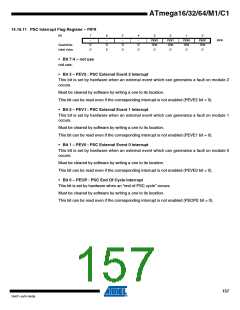
14.16.11 PSC Interrupt Flag Register – PIFR
Bit
7
-
6
-
5
-
4
-
3
PEV2
R/W
0
2
PEV1
R/W
0
1
PEV0
R/W
0
0
PEOP
R/W
0
PIFR
Read/Write
Initial Value
R
0
R
0
R
0
R
0
• Bit 7:4 – not use
not use.
• Bit 3 – PEV2 : PSC External Event 2 Interrupt
This bit is set by hardware when an external event which can generates a fault on module 2
occurs.
Must be cleared by software by writing a one to its location.
This bit can be read even if the corresponding interrupt is not enabled (PEVE2 bit = 0).
• Bit 2 – PEV1 : PSC External Event 1 Interrupt
This bit is set by hardware when an external event which can generates a fault on module 1
occurs.
Must be cleared by software by writing a one to its location.
This bit can be read even if the corresponding interrupt is not enabled (PEVE1 bit = 0).
• Bit 1 – PEV0 : PSC External Event 0 Interrupt
This bit is set by hardware when an external event which can generates a fault on module 0
occurs.
Must be cleared by software by writing a one to its location.
This bit can be read even if the corresponding interrupt is not enabled (PEVE0 bit = 0).
• Bit 0 – PEOP : PSC End Of Cycle Interrupt
This bit is set by hardware when an “end of PSC cycle” occurs.
Must be cleared by software by writing a one to its location.
This bit can be read even if the corresponding interrupt is not enabled (PEOPE bit = 0).
157
7647F–AVR–04/09

 ATMEL [ ATMEL ]