ATmega8(L)
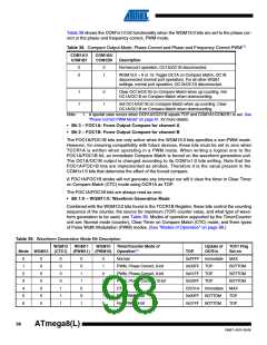
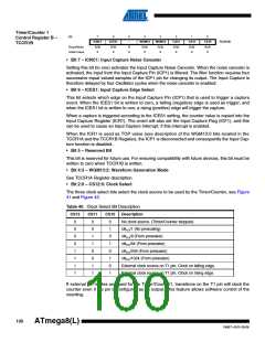
Table 39. Waveform Generation Mode Bit Description
WGM12
(CTC1)
WGM11
WGM10
Timer/Counter Mode of
Update of
OCR1x
TOV1 Flag
Set on
Mode WGM13
(PWM11) (PWM10) Operation(1)
TOP
7
0
1
1
1
1
1
1
1
1
1
0
0
0
0
1
1
1
1
1
0
0
1
1
0
0
1
1
1
0
1
0
1
0
1
0
1
Fast PWM, 10-bit
0x03FF
BOTTOM
BOTTOM
TOP
8
PWM, Phase and Frequency Correct ICR1
BOTTOM
BOTTOM
BOTTOM
BOTTOM
MAX
9
PWM, Phase and Frequency Correct OCR1A BOTTOM
10
11
12
13
14
PWM, Phase Correct
PWM, Phase Correct
CTC
ICR1
TOP
OCR1A TOP
ICR1
–
Immediate
(Reserved)
–
–
Fast PWM
ICR1
BOTTOM
TOP
15
Fast PWM
OCR1A BOTTOM
TOP
Note:
1. The CTC1 and PWM11:0 bit definition names are obsolete. Use the WGM12:0 definitions. However, the functionality and
location of these bits are compatible with previous versions of the timer.
99
2486T–AVR–05/08

 ATMEL [ ATMEL ]