ATmega8(L)
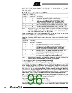
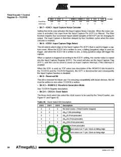
what type of waveform generation to be used, see Table 39. Modes of operation sup-
ported by the Timer/Counter unit are: Normal mode (counter), Clear Timer on Compare
Match (CTC) mode, and three types of Pulse Width Modulation (PWM) modes. (See
“Modes of Operation” on page 86.)
Table 39. Waveform Generation Mode Bit Description
WGM12
(CTC1)
WGM11
WGM10
Timer/Counter Mode of
Update of
OCR1x
TOV1 Flag
Set on
Mode WGM13
(PWM11) (PWM10) Operation(1)
TOP
0
1
2
3
4
5
6
7
8
0
0
0
0
0
0
0
0
1
0
0
0
0
1
1
1
1
0
0
0
1
1
0
0
1
1
0
0
1
0
1
0
1
0
1
0
Normal
0xFFFF Immediate
MAX
PWM, Phase Correct, 8-bit
PWM, Phase Correct, 9-bit
PWM, Phase Correct, 10-bit
CTC
0x00FF
0x01FF
0x03FF
TOP
TOP
TOP
BOTTOM
BOTTOM
BOTTOM
MAX
OCR1A Immediate
Fast PWM, 8-bit
0x00FF
0x01FF
0x03FF
ICR1
TOP
TOP
Fast PWM, 9-bit
TOP
TOP
Fast PWM, 10-bit
TOP
TOP
PWM, Phase and Frequency
Correct
BOTTOM
BOTTOM
9
1
0
0
1
PWM, Phase and Frequency
Correct
OCR1A BOTTOM
BOTTOM
10
11
12
13
14
1
1
1
1
1
1
0
0
1
1
1
1
1
1
0
0
1
1
0
1
0
1
0
1
PWM, Phase Correct
PWM, Phase Correct
CTC
ICR1
TOP
BOTTOM
BOTTOM
MAX
OCR1A TOP
ICR1
–
Immediate
(Reserved)
–
–
Fast PWM
ICR1
TOP
TOP
15
Fast PWM
OCR1A TOP
TOP
Note:
1. The CTC1 and PWM11:0 bit definition names are obsolete. Use the WGM12:0 definitions. However, the functionality and
location of these bits are compatible with previous versions of the timer.
97
2486M–AVR–12/03

 ATMEL [ ATMEL ]