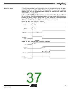
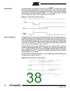
ATmega8(L)
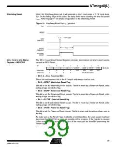
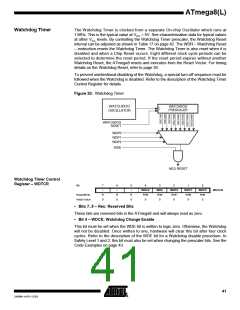
Watchdog Timer
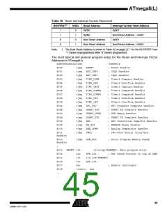
The Watchdog Timer is clocked from a separate On-chip Oscillator which runs at
1 MHz. This is the typical value at VCC = 5V. See characterization data for typical values
at other VCC levels. By controlling the Watchdog Timer prescaler, the Watchdog Reset
interval can be adjusted as shown in Table 17 on page 42. The WDR – Watchdog Reset
– instruction resets the Watchdog Timer. The Watchdog Timer is also reset when it is
disabled and when a Chip Reset occurs. Eight different clock cycle periods can be
selected to determine the reset period. If the reset period expires without another
Watchdog Reset, the ATmega8 resets and executes from the Reset Vector. For timing
details on the Watchdog Reset, refer to page 39.
To prevent unintentional disabling of the Watchdog, a special turn-off sequence must be
followed when the Watchdog is disabled. Refer to the description of the Watchdog Timer
Control Register for details.
Figure 20. Watchdog Timer
WATCHDOG
OSCILLATOR
Watchdog Timer Control
Register – WDTCR
Bit
7
–
6
–
5
–
4
WDCE
R/W
0
3
WDE
R/W
0
2
WDP2
R/W
0
1
WDP1
R/W
0
0
WDP0
R/W
0
WDTCR
Read/Write
Initial Value
R
0
R
0
R
0
• Bits 7..5 – Res: Reserved Bits
These bits are reserved bits in the ATmega8 and will always read as zero.
• Bit 4 – WDCE: Watchdog Change Enable
This bit must be set when the WDE bit is written to logic zero. Otherwise, the Watchdog
will not be disabled. Once written to one, hardware will clear this bit after four clock
cycles. Refer to the description of the WDE bit for a Watchdog disable procedure. In
Safety Level 1 and 2, this bit must also be set when changing the prescaler bits. See the
Code Examples on page 43.
41
2486M–AVR–12/03

 ATMEL [ ATMEL ]