ATmega8(L)
Watchdog Reset
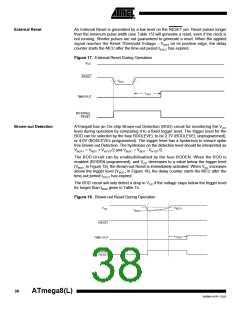
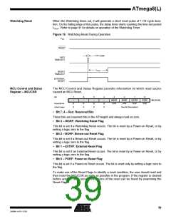
When the Watchdog times out, it will generate a short reset pulse of 1 CK cycle dura-
tion. On the falling edge of this pulse, the delay timer starts counting the time-out period
tTOUT. Refer to page 41 for details on operation of the Watchdog Timer.
Figure 19. Watchdog Reset During Operation
CC
CK
MCU Control and Status
Register – MCUCSR
The MCU Control and Status Register provides information on which reset source
caused an MCU Reset.
Bit
7
–
6
–
5
–
4
–
3
2
1
0
WDRF
R/W
BORF
R/W
EXTRF
R/W
PORF
R/W
MCUCSR
Read/Write
Initial Value
R
0
R
0
R
0
R
0
See Bit Description
• Bit 7..4 – Res: Reserved Bits
These bits are reserved bits in the ATmega8 and always read as zero.
• Bit 3 – WDRF: Watchdog Reset Flag
This bit is set if a Watchdog Reset occurs. The bit is reset by a Power-on Reset, or by
writing a logic zero to the flag.
• Bit 2 – BORF: Brown-out Reset Flag
This bit is set if a Brown-out Reset occurs. The bit is reset by a Power-on Reset, or by
writing a logic zero to the flag.
• Bit 1 – EXTRF: External Reset Flag
This bit is set if an External Reset occurs. The bit is reset by a Power-on Reset, or by
writing a logic zero to the flag.
• Bit 0 – PORF: Power-on Reset Flag
This bit is set if a Power-on Reset occurs. The bit is reset only by writing a logic zero to
the flag.
To make use of the Reset Flags to identify a reset condition, the user should read and
then reset the MCUCSR as early as possible in the program. If the register is cleared
before another reset occurs, the source of the reset can be found by examining the
Reset Flags.
39
2486M–AVR–12/03

 ATMEL [ ATMEL ]