Interrupts
This section describes the specifics of the interrupt handling performed by the
ATmega8. For a general explanation of the AVR interrupt handling, refer to “Reset and
Interrupt Handling” on page 12.
Interrupt Vectors in
ATmega8
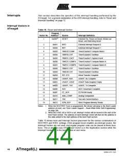
Table 18. Reset and Interrupt Vectors
Program
Vector No. Address(2) Source
Interrupt Definition
1
0x000(1)
RESET
External Pin, Power-on Reset, Brown-out
Reset, and Watchdog Reset
2
3
0x001
0x002
0x003
0x004
0x005
0x006
0x007
0x008
0x009
0x00A
0x00B
0x00C
0x00D
0x00E
0x00F
0x010
0x011
0x012
INT0
External Interrupt Request 0
External Interrupt Request 1
Timer/Counter2 Compare Match
Timer/Counter2 Overflow
INT1
4
TIMER2 COMP
TIMER2 OVF
TIMER1 CAPT
5
6
Timer/Counter1 Capture Event
7
TIMER1 COMPA Timer/Counter1 Compare Match A
TIMER1 COMPB Timer/Counter1 Compare Match B
8
9
TIMER1 OVF
TIMER0 OVF
SPI, STC
Timer/Counter1 Overflow
Timer/Counter0 Overflow
Serial Transfer Complete
USART, Rx Complete
10
11
12
13
14
15
16
17
18
19
USART, RXC
USART, UDRE
USART, TXC
ADC
USART Data Register Empty
USART, Tx Complete
ADC Conversion Complete
EEPROM Ready
EE_RDY
ANA_COMP
TWI
Analog Comparator
Two-wire Serial Interface
Store Program Memory Ready
SPM_RDY
Notes: 1. When the BOOTRST Fuse is programmed, the device will jump to the Boot Loader
address at reset, see “Boot Loader Support – Read-While-Write Self-Programming”
on page 206.
2. When the IVSEL bit in GICR is set, Interrupt Vectors will be moved to the start of the
boot Flash section. The address of each Interrupt Vector will then be the address in
this table added to the start address of the boot Flash section.
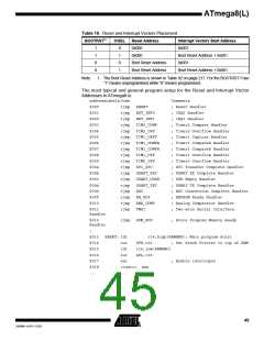
Table 19 shows reset and Interrupt Vectors placement for the various combinations of
BOOTRST and IVSEL settings. If the program never enables an interrupt source, the
Interrupt Vectors are not used, and regular program code can be placed at these loca-
tions. This is also the case if the Reset Vector is in the Application section while the
Interrupt Vectors are in the boot section or vice versa.
44
ATmega8(L)
2486M–AVR–12/03

 ATMEL [ ATMEL ]