Reading the Signature Bytes
The algorithm for reading the Signature bytes is as follows (refer to “Programming the
Flash” on page 225 for details on Command and Address loading):
1. A: Load Command “0000 1000”.
2. B: Load Address Low byte (0x00 - 0x02).
3. Set OE to “0”, and BS1 to “0”. The selected Signature byte can now be read at
DATA.
4. Set OE to “1”.
Reading the Calibration Byte
The algorithm for reading the Calibration bytes is as follows (refer to “Programming the
Flash” on page 225 for details on Command and Address loading):
1. A: Load Command “0000 1000”.
2. B: Load Address Low byte, (0x00 - 0x03).
3. Set OE to “0”, and BS1 to “1”. The Calibration byte can now be read at DATA.
4. Set OE to “1”.
Parallel Programming
Characteristics
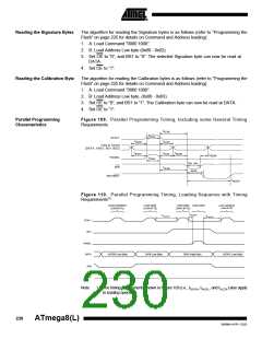
Figure 109. Parallel Programming Timing, Including some General Timing
Requirements
tXLWL
tXHXL
XTAL1
tDVXH
tXLDX
Data & Contol
(DATA, XA0/1, BS1, BS2)
tBVPH
tPLBX
t BVWL
tWLBX
PAGEL
tPHPL
tWL WH
WR
tPLWL
WLRL
RDY/BSY
tWLRH
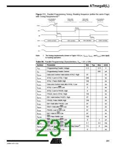
Figure 110. Parallel Programming Timing, Loading Sequence with Timing
Requirements(1)
LOAD DATA
LOAD ADDRESS
(LOW BYTE)
LOAD DATA
(LOW BYTE)
LOAD DATA
(HIGH BYTE)
LOAD ADDRESS
(LOW BYTE)
tXLPH
tXLXH
tPLXH
XTAL1
BS1
PAGEL
DATA
ADDR0 (Low Byte)
DATA (Low Byte)
DATA (High Byte)
ADDR1 (Low Byte)
XA0
XA1
Note:
1. The timing requirements shown in Figure 109 (i.e., tDVXH, tXHXL, and tXLDX) also apply
to loading operation.
230
ATmega8(L)
2486M–AVR–12/03

 ATMEL [ ATMEL ]