ATmega8(L)
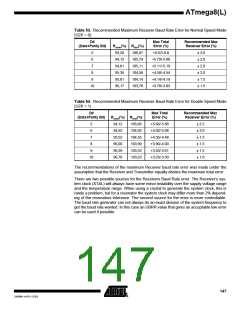
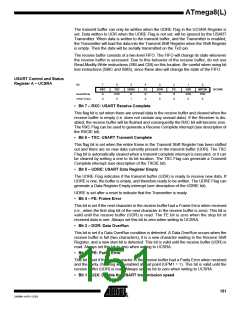
Table 53. Recommended Maximum Receiver Baud Rate Error for Normal Speed Mode
(U2X = 0)
D#
Max Total
Error (%)
Recommended Max
Receiver Error (%)
(Data+Parity Bit)
Rslow(%) Rfast(%)
5
6
93,20
94,12
94,81
95,36
95,81
96,17
106,67
105,79
105,11
104,58
104,14
103,78
+6.67/-6.8
+5.79/-5.88
+5.11/-5.19
+4.58/-4.54
+4.14/-4.19
+3.78/-3.83
± 3.0
± 2.0
± 2.0
± 2.0
± 1.5
± 1.5
7
8
9
10
Table 54. Recommended Maximum Receiver Baud Rate Error for Double Speed Mode
(U2X = 1)
D#
Max Total
Error (%)
Recommended Max
Receiver Error (%)
(Data+Parity Bit)
Rslow(%) Rfast(%)
5
6
94,12
94,92
95,52
96,00
96,39
96,70
105,66
104,92
104,35
103,90
103,53
103,23
+5.66/-5.88
+4.92/-5.08
+4.35/-4.48
+3.90/-4.00
+3.53/-3.61
+3.23/-3.30
± 2.5
± 2.0
± 1.5
± 1.5
± 1.5
± 1.0
7
8
9
10
The recommendations of the maximum Receiver baud rate error was made under the
assumption that the Receiver and Transmitter equally divides the maximum total error.
There are two possible sources for the Receivers Baud Rate error. The Receiver’s sys-
tem clock (XTAL) will always have some minor instability over the supply voltage range
and the temperature range. When using a crystal to generate the system clock, this is
rarely a problem, but for a resonator the system clock may differ more than 2% depend-
ing of the resonators tolerance. The second source for the error is more controllable.
The baud rate generator can not always do an exact division of the system frequency to
get the baud rate wanted. In this case an UBRR value that gives an acceptable low error
can be used if possible.
147
2486M–AVR–12/03

 ATMEL [ ATMEL ]