SPI Data Modes and
Timing
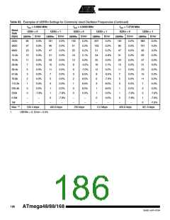
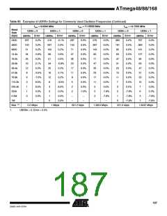
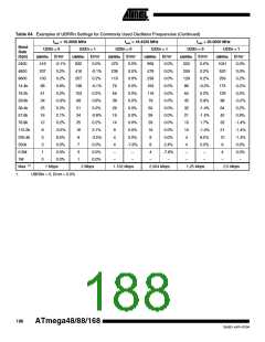
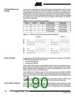
There are four combinations of XCKn (SCK) phase and polarity with respect to serial
data, which are determined by control bits UCPHAn and UCPOLn. The data transfer
timing diagrams are shown in Figure 77. Data bits are shifted out and latched in on
opposite edges of the XCKn signal, ensuring sufficient time for data signals to stabilize.
The UCPOLn and UCPHAn functionality is summarized in Table 86. Note that changing
the setting of any of these bits will corrupt all ongoing communication for both the
Receiver and Transmitter.
Table 86. UCPOLn and UCPHAn Functionality-
UCPOLn
UCPHAn
SPI Mode
Leading Edge
Sample (Rising)
Setup (Rising)
Sample (Falling)
Setup (Falling)
Trailing Edge
Setup (Falling)
Sample (Falling)
Setup (Rising)
Sample (Rising)
0
0
1
1
0
1
0
1
0
1
2
3
Figure 77. UCPHAn and UCPOLn data transfer timing diagrams.
UCPOL=0
UCPOL=1
XCK
XCK
Data setup (TXD)
Data sample (RXD)
Data setup (TXD)
Data sample (RXD)
XCK
XCK
Data setup (TXD)
Data sample (RXD)
Data setup (TXD)
Data sample (RXD)
Frame Formats
A serial frame for the MSPIM is defined to be one character of 8 data bits. The USART
in MSPIM mode has two valid frame formats:
•
•
8-bit data with MSB first
8-bit data with LSB first
A frame starts with the least or most significant data bit. Then the next data bits, up to a
total of eight, are succeeding, ending with the most or least significant bit accordingly.
When a complete frame is transmitted, a new frame can directly follow it, or the commu-
nication line can be set to an idle (high) state.
The UDORDn bit in UCSRnC sets the frame format used by the USART in MSPIM
mode. The Receiver and Transmitter use the same setting. Note that changing the set-
ting of any of these bits will corrupt all ongoing communication for both the Receiver and
Transmitter.
16-bit data transfer can be achieved by writing two data bytes to UDRn. A UART trans-
mit complete interrupt will then signal that the 16-bit value has been shifted out.
USART MSPIM Initialization
The USART in MSPIM mode has to be initialized before any communication can take
place. The initialization process normally consists of setting the baud rate, setting mas-
ter mode of operation (by setting DDR_XCKn to one), setting frame format and enabling
190
ATmega48/88/168
2545D–AVR–07/04

 ATMEL [ ATMEL ]