ATmega48/88/168
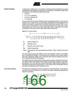
If used, the parity bit is located between the last data bit and first stop bit of a serial
frame.
USART Initialization
The USART has to be initialized before any communication can take place. The initial-
ization process normally consists of setting the baud rate, setting frame format and
enabling the Transmitter or the Receiver depending on the usage. For interrupt driven
USART operation, the Global Interrupt Flag should be cleared (and interrupts globally
disabled) when doing the initialization.
Before doing a re-initialization with changed baud rate or frame format, be sure that
there are no ongoing transmissions during the period the registers are changed. The
TXCn Flag can be used to check that the Transmitter has completed all transfers, and
the RXC Flag can be used to check that there are no unread data in the receive buffer.
Note that the TXCn Flag must be cleared before each transmission (before UDRn is
written) if it is used for this purpose.
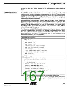
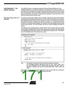
The following simple USART initialization code examples show one assembly and one
C function that are equal in functionality. The examples assume asynchronous opera-
tion using polling (no interrupts enabled) and a fixed frame format. The baud rate is
given as a function parameter. For the assembly code, the baud rate parameter is
assumed to be stored in the r17:r16 Registers.
Assembly Code Example(1)
USART_Init:
; Set baud rate
out UBRRnH, r17
out UBRRnL, r16
; Enable receiver and transmitter
ldi r16, (1<<RXENn)|(1<<TXENn)
out UCSRnB,r16
; Set frame format: 8data, 2stop bit
ldi r16, (1<<USBSn)|(3<<UCSZn0)
out UCSRnC,r16
ret
C Code Example(1)
void USART_Init( unsigned int baud )
{
/* Set baud rate */
UBRRnH = (unsigned char)(baud>>8);
UBRRnL = (unsigned char)baud;
/* Enable receiver and transmitter */
UCSRnB = (1<<RXENn)|(1<<TXENn);
/* Set frame format: 8data, 2stop bit */
UCSRnC = (1<<USBSn)|(3<<UCSZn0);
}
Note:
1. The example code assumes that the part specific header file is included.
For I/O Registers located in extended I/O map, “IN”, “OUT”, “SBIS”, “SBIC”, “CBI”,
and “SBI” instructions must be replaced with instructions that allow access to
167
2545D–AVR–07/04

 ATMEL [ ATMEL ]