ATmega640/1280/1281/2560/2561
Watchdog Reset
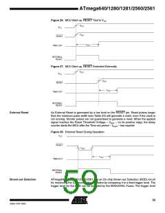
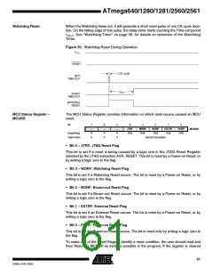
When the Watchdog times out, it will generate a short reset pulse of one CK cycle dura-
tion. On the falling edge of this pulse, the delay timer starts counting the Time-out period
t
TOUT. See “Watchdog Timer” on page 56. for details on operation of the Watchdog
Timer.
Figure 30. Watchdog Reset During Operation
CC
CK
MCU Status Register –
MCUSR
The MCU Status Register provides information on which reset source caused an MCU
reset.
Bit
7
–
6
–
5
–
4
3
2
1
0
JTRF
R/W
WDRF
R/W
BORF
R/W
EXTRF
R/W
PORF
R/W
MCUSR
Read/Write
Initial Value
R
0
R
0
R
0
See Bit Description
• Bit 4 – JTRF: JTAG Reset Flag
This bit is set if a reset is being caused by a logic one in the JTAG Reset Register
selected by the JTAG instruction AVR_RESET. This bit is reset by a Power-on Reset, or
by writing a logic zero to the flag.
• Bit 3 – WDRF: Watchdog Reset Flag
This bit is set if a Watchdog Reset occurs. The bit is reset by a Power-on Reset, or by
writing a logic zero to the flag.
• Bit 2 – BORF: Brown-out Reset Flag
This bit is set if a Brown-out Reset occurs. The bit is reset by a Power-on Reset, or by
writing a logic zero to the flag.
• Bit 1 – EXTRF: External Reset Flag
This bit is set if an External Reset occurs. The bit is reset by a Power-on Reset, or by
writing a logic zero to the flag.
• Bit 0 – PORF: Power-on Reset Flag
This bit is set if a Power-on Reset occurs. The bit is reset only by writing a logic zero to
the flag.
To make use of the Reset Flags to identify a reset condition, the user should read and
then Reset the MCUSR as early as possible in the program. If the register is cleared
61
2549A–AVR–03/05

 ATMEL [ ATMEL ]