1. In the same operation, write a logic one to the Watchdog change enable bit
(WDCE) and WDE. A logic one must be written to WDE regardless of the previ-
ous value of the WDE bit.
2. Within the next four clock cycles, write the WDE and Watchdog prescaler bits
(WDP) as desired, but with the WDCE bit cleared. This must be done in one
operation.
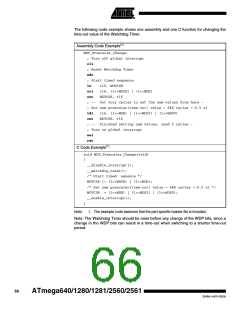
The following code example shows one assembly and one C function for turning off the
Watchdog Timer. The example assumes that interrupts are controlled (e.g. by disabling
interrupts globally) so that no interrupts will occur during the execution of these
functions.
64
ATmega640/1280/1281/2560/2561
2549A–AVR–03/05

 ATMEL [ ATMEL ]