has a hysteresis to ensure spike free Brown-out Detection. The hysteresis on the detec-
tion level should be interpreted as VBOT+ = VBOT + VHYST/2 and VBOT- = VBOT - VHYST/2.
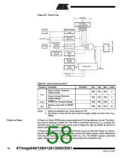
Table 24. BODLEVEL Fuse Coding(1)
BODLEVEL 2..0 Fuses
Min VBOT
Typ VBOT
Max VBOT
Units
111
110
101
100
011
010
001
000
BOD Disabled
1.8
2.7
4.3
V
Reserved
Note:
1. VBOT may be below nominal minimum operating voltage for some devices. For
devices where this is the case, the device is tested down to VCC = VBOT during the
production test. This guarantees that a Brown-Out Reset will occur before VCC drops
to a voltage where correct operation of the microcontroller is no longer guaranteed.
The
test
is
performed
using
and
BODLEVEL = 110
BODLEVEL = 101
for
for
ATmega640/1280/1281/2560/2561
ATmega640/1280/2560/1L.
Table 25. Brown-out Characteristics
Symbol
VHYST
tBOD
Parameter
Min
Typ
Max
Units
mV
Brown-out Detector Hysteresis
Min Pulse Width on Brown-out Reset
50
ns
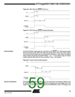
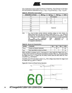
When the BOD is enabled, and VCC decreases to a value below the trigger level (VBOT-
in Figure 29), the Brown-out Reset is immediately activated. When VCC increases above
the trigger level (VBOT+ in Figure 29), the delay counter starts the MCU after the Time-
out period tTOUT has expired.
The BOD circuit will only detect a drop in VCC if the voltage stays below the trigger level
for longer than tBOD given in Table 23.
Figure 29. Brown-out Reset During Operation
VBOT+
VCC
VBOT-
RESET
t
TOUT
TIME-OUT
INTERNAL
RESET
60
ATmega640/1280/1281/2560/2561
2549A–AVR–03/05

 ATMEL [ ATMEL ]