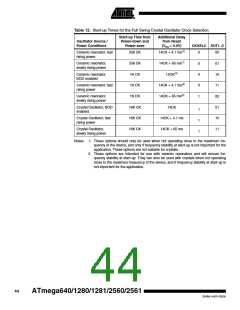
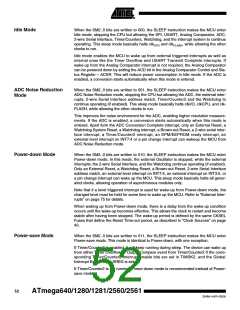
Table 19. Start-up Times for the External Clock Selection
Start-up Time from Power-
down and Power-save
Additional Delay from
Reset (VCC = 5.0V)
Power Conditions
BOD enabled
SUT1..0
00
6 CK
6 CK
14CK
Fast rising power
Slowly rising power
14CK + 4.1 ms
14CK + 65 ms
01
6 CK
10
Reserved
11
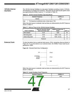
When applying an external clock, it is required to avoid sudden changes in the applied
clock frequency to ensure stable operation of the MCU. A variation in frequency of more
than 2ꢀ from one clock cycle to the next can lead to unpredictable behavior. If changes
of more than 2ꢀ is required, ensure that the MCU is kept in Reset during the changes.
Note that the System Clock Prescaler can be used to implement run-time changes of
the internal clock frequency while still ensuring stable operation. Refer to “System Clock
Prescaler” on page 48 for details.
Clock Output Buffer
The device can output the system clock on the CLKO pin. To enable the output, the
CKOUT Fuse has to be programmed. This mode is suitable when the chip clock is used
to drive other circuits on the system. The clock also will be output during reset, and the
normal operation of I/O pin will be overridden when the fuse is programmed. Any clock
source, including the internal RC Oscillator, can be selected when the clock is output on
CLKO. If the System Clock Prescaler is used, it is the divided system clock that is
output.
Timer/Counter Oscillator The device can operate its Timer/Counter2 from an external 32.768 kHz watch crystal or
a external clock source. See Figure 22 on page 41 for crystal connection.
Applying an external clock source to TOSC1 requires EXCLK in the ASSR Register writ-
ten to logic one. See “Asynchronous operation of the Timer/Counter” on page 189 for
further description on selecting external clock as input instead of a 32 kHz crystal.
System Clock Prescaler
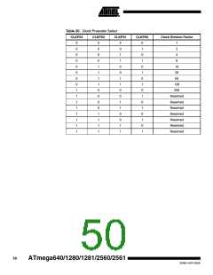
The ATmega640/1280/1281/2560/2561 has a system clock prescaler, and the system
clock can be divided by setting the “Clock Prescale Register – CLKPR” on page 49. This
feature can be used to decrease the system clock frequency and the power consump-
tion when the requirement for processing power is low. This can be used with all clock
source options, and it will affect the clock frequency of the CPU and all synchronous
peripherals. clkI/O, clkADC, clkCPU, and clkFLASH are divided by a factor as shown in Table
20.
When switching between prescaler settings, the System Clock Prescaler ensures that
no glitches occurs in the clock system. It also ensures that no intermediate frequency is
higher than neither the clock frequency corresponding to the previous setting, nor the
clock frequency corresponding to the new setting.
The ripple counter that implements the prescaler runs at the frequency of the undivided
clock, which may be faster than the CPU's clock frequency. Hence, it is not possible to
determine the state of the prescaler - even if it were readable, and the exact time it takes
to switch from one clock division to the other cannot be exactly predicted. From the time
the CLKPS values are written, it takes between T1 + T2 and T1 + 2 * T2 before the new
clock frequency is active. In this interval, 2 active clock edges are produced. Here, T1 is
48
ATmega640/1280/1281/2560/2561
2549A–AVR–03/05

 ATMEL [ ATMEL ]