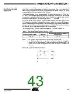
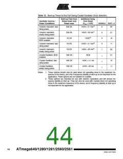
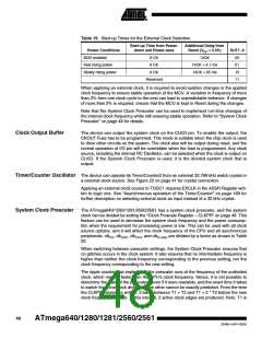
Table 12. Start-up Times for the Full Swing Crystal Oscillator Clock Selection
Start-up Time from
Power-down and
Power-save
Additional Delay
from Reset
Oscillator Source /
Power Conditions
(VCC = 5.0V)
CKSEL0 SUT1..0
Ceramic resonator, fast
rising power
258 CK
258 CK
1K CK
14CK + 4.1 ms(1)
14CK + 65 ms(1)
14CK(2)
0
0
0
0
1
00
01
10
11
00
01
10
11
Ceramic resonator,
slowly rising power
Ceramic resonator,
BOD enabled
Ceramic resonator, fast
rising power
1K CK
14CK + 4.1 ms(2)
14CK + 65 ms(2)
14CK
Ceramic resonator,
slowly rising power
1K CK
Crystal Oscillator, BOD
enabled
16K CK
16K CK
16K CK
1
1
1
Crystal Oscillator, fast
rising power
14CK + 4.1 ms
14CK + 65 ms
Crystal Oscillator,
slowly rising power
Notes: 1. These options should only be used when not operating close to the maximum fre-
quency of the device, and only if frequency stability at start-up is not important for the
application. These options are not suitable for crystals.
2. These options are intended for use with ceramic resonators and will ensure fre-
quency stability at start-up. They can also be used with crystals when not operating
close to the maximum frequency of the device, and if frequency stability at start-up is
not important for the application.
44
ATmega640/1280/1281/2560/2561
2549A–AVR–03/05

 ATMEL [ ATMEL ]